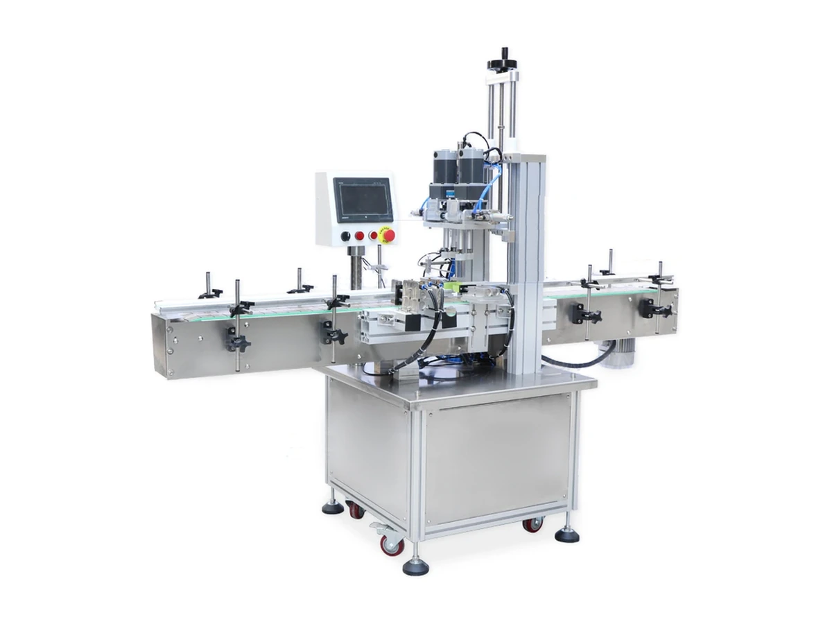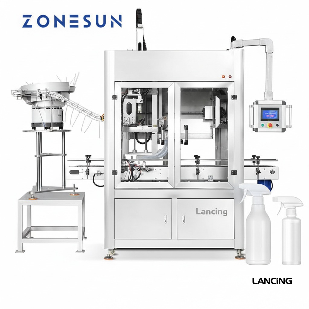
Bulk loading
Pump closures are loaded into the configured feeding system.
Closure feeding and placement
A dedicated machine for automatically presenting, picking and placing pump closures before a separate tightening station or integrated capping section.
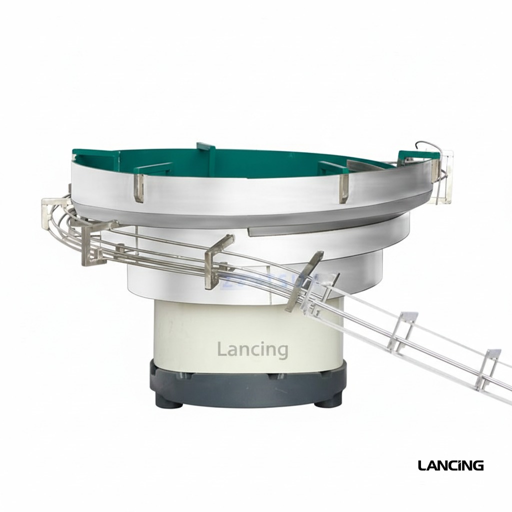
Where it fits
A dedicated machine for automatically presenting, picking and placing pump closures before a separate tightening station or integrated capping section.
Pump capping performance is governed by the complete pack. Bottle support, dip-tube insertion, pump-head orientation and thread engagement are developed together, using approved samples and a documented production requirement.
Project specification
The final specification is developed from approved bottle and pump samples, required output, line interfaces, site standards and documented acceptance criteria.
All performance and dimensions are indicative. Exact configuration and output are subject to approved samples, product information, agreed trials and final quotation.
| Configuration | Automatic pump-cap feeding and placement module |
|---|---|
| Output basis | Matched to the required downstream capping rate and confirmed by trial |
| Closure compatibility | Custom-engineered to approved pump samples |
| Bottle compatibility | Configured to approved bottles and line handling |
| Electrical requirements | Confirmed for the final feeder and controls package |
| Pneumatic requirements | Confirmed after pick-and-place tooling design |
| Footprint | Confirmed on the approved line-layout technical file |
Operating sequence
The final sequence is tailored to the selected closure feeder, bottle format and upstream/downstream interfaces.
Pump closures are loaded into the configured feeding system.
Closures are separated and presented one at a time.
The head and dip tube are controlled to suit the placement method.
A pneumatic mechanism transfers the pump to the bottle.
The loosely placed pump proceeds to the specified tightening station.
Sample-led engineering
Reliable pump automation is proven with representative components rather than inferred from nominal dimensions.
Every size and shape, ideally decorated and at representative filled weight.
Production closures showing normal tube length, curvature, packing and batch variation.
Required sustained rate, shift pattern, batch size and expected line efficiency.
Torque, height, direction, leakage, cosmetic and reject acceptance criteria.
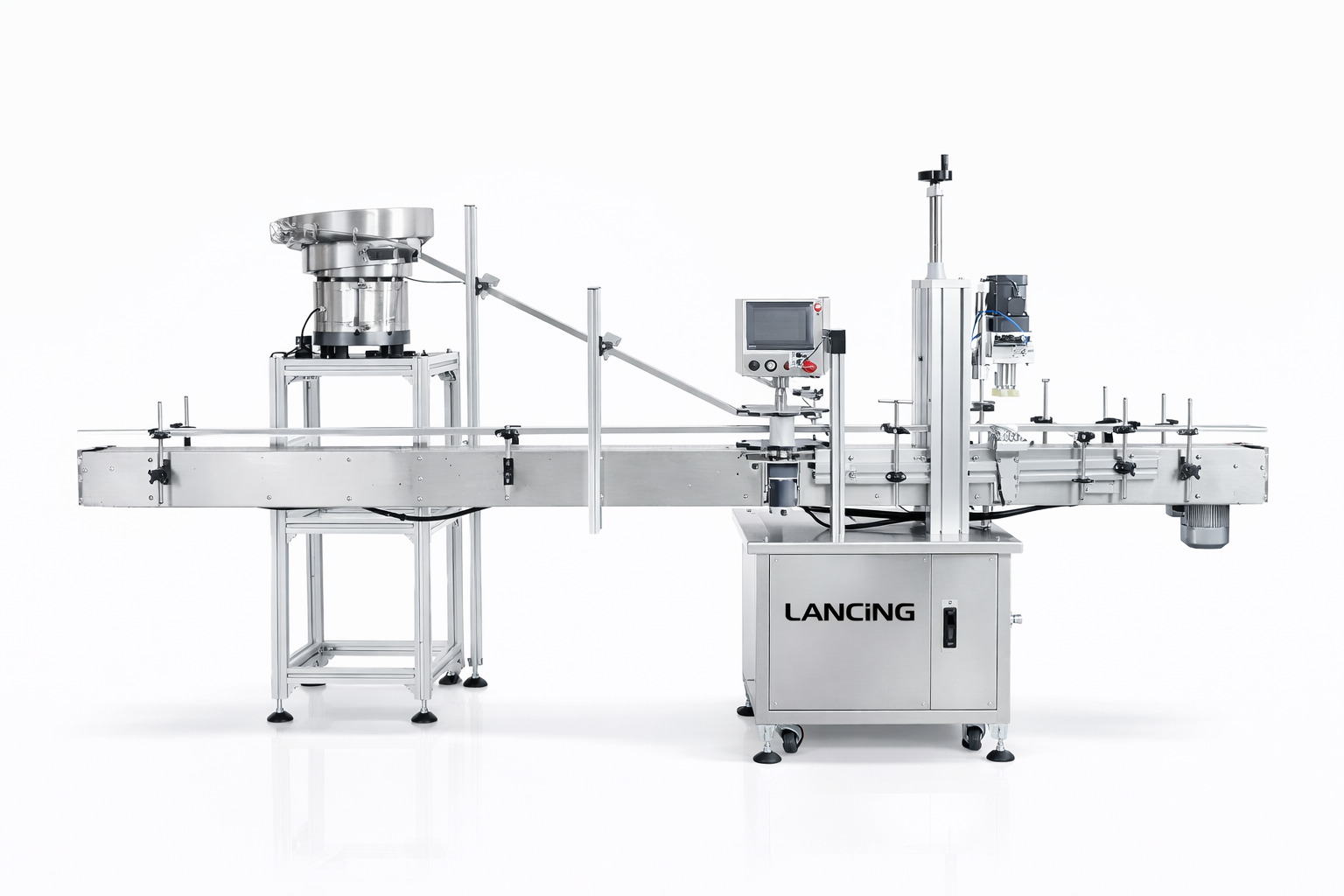
Machine views
These real product photographs show representative equipment and process details. Your final configuration is confirmed against approved bottles, pumps and project requirements.
Practical answers
Every pump format behaves differently. Final machine selection and performance are confirmed through sample review and agreed trials.
Suitability depends on the complete bottle-and-pump combination, not only nominal diameter. Closure head shape, tube length and curvature, neck finish, filled weight and final presentation are reviewed before a configuration is confirmed.
Output is matched to the downstream capping rate. Actual sustained output depends on the approved pack, feeding method, changeover, operator or line interfaces and agreed acceptance conditions. The project quotation states the tested or warranted basis.
Usually, provided each format falls within the engineered handling range. Some changes may be tool-free; others require guides, chucks, pockets, pump transfer parts or recipe changes. Supply the complete format matrix at enquiry stage.
The method depends on the closure. Directional actuators may be oriented in the feeder, during placement, by controlled thread engagement or in a separate orientation step. Exact directional tolerance must be agreed during testing.
Send representative bottles and pumps from normal production supply, including labelled or decorated bottles where marking is a concern. Filled-weight samples or safe ballast, component technical files and expected variation are also valuable.
Related machinery
Configured inline system
A flexible automatic screw-capping platform for suitable spray and pump closures, using in-line bottle control and powered capping modules.
View machine detailsCustom trigger sprayer capper
An automatic capping system engineered for trigger sprayers and dispenser pumps whose head shape, actuator direction and long dip tube require positive orientation and bottle control.
View machine detailsGuarded automatic configuration
A guarded automatic capping platform that can be assessed for pump-compatible applications where enclosure, controlled access and an integrated production-cell format are required.
View machine detailsNext step
Send sample photographs, dimensions, planned formats and target output. Physical samples are used to confirm handling and the final machine specification.
Verified reference configuration
A pump feeder is not a standalone promise of line output. Its value depends on separating the supplied pumps, retaining orientation and handing each closure to the downstream process at the required time.
The published reference establishes a starting capacity, utilities and layout. Final suitability depends on the pump head, collar, dip tube, bulk packing and the transfer requested by the capping machine. The feeder, buffer and capper should be trialled as one controlled system because a pump that leaves the feeder correctly can still lose orientation or catch during handover.
See the Lancing LU-XG445S reference page for the first-party data. For projects whose primary intent is feeder selection rather than the complete pump-capping line, use the dedicated Cap Feeders UK route.
Document the required actuator direction and the pump feature used for orientation. Long soft tubes may trail unpredictably, retain curvature or enter neighbouring components. The chosen rail, gripper or pneumatic pick should support the closure without crushing the actuator, dragging the tube or allowing the pump to rotate before placement.
| Published Lancing reference | LU-XG445S reference value |
|---|---|
| Machine model | LU-XG445S |
| Capacity | 5–25 bottles/min, based on bottle and cap size |
| Voltage | 110 V / 220 V |
| Power | 1.5 kW |
| Air pressure | 0.5–0.8 MPa |
| Cap feeding way | Pneumatic fetch |
| Machine size | About 3000 × 1300 × 2100 mm |
The approved rate must include the pump supply method, downstream demand, transfer and normal recovery conditions.
Controls and recovery
A feeder should support the capper without flooding the transfer, starving the placement station or concealing repeated component faults.
Agree which machine controls demand, how pump-present and buffer-level signals are generated, and what the feeder does during a capper stop. Accumulation should retain orientation without compressing actuators or trapping dip tubes. Low-level and empty conditions should be visible early enough for replenishment without unnecessary line stops.
Define where malformed, doubled or wrongly oriented pumps are rejected and how the operator reaches them. A jam should not be cleared by pulling a tube through the mechanism or disturbing calibrated rails. After recovery, the control sequence should confirm the next valid pump and bottle before placement resumes.
List all rails, guides, sensors, picks, tube supports and recipes that change. Record reference marks and approved settings. Inspect areas where tubes rub or components collect; residues, label fragments and damaged pumps can alter friction and increase misfeeds even when the mechanical setting has not changed.
Document electrical and pneumatic interfaces, emergency-stop boundaries, ready/running/fault signals, demand logic and the physical transfer height. Confirm whether the feeder is supplied as part of the capper cell or interfaces to separate equipment, and identify responsibility for the handover point in the final specification.
Project review
Send pumps in their normal bulk packing, bottle samples, target output and the proposed downstream interface so presentation and handover can be assessed together.
Component characterisation
A pump feeder is influenced by the complete closure and the way it arrives from production supply. Dimensions alone do not show how heads interlock, how tubes retain curvature or how the pump behaves when the hopper is replenished.
| Pump feature | Evidence to record | Why it affects feeding and placement |
|---|---|---|
| Actuator and nozzle geometry | Overall shape, offset, lock state, preferred final direction and surfaces that may be gripped. | Controls orientation, centre of mass, nesting and the safe contact point for transfer tooling. |
| Collar and thread area | Drive surface, diameter, skirt depth, tamper feature and the relationship to the bottle neck. | Determines how the pump is located, held and released without affecting later thread engagement. |
| Dip-tube free length | Length below the collar, cut condition and shortest/longest approved variants. | Changes tangling risk, required clearance and the insertion path into the bottle. |
| Tube stiffness and retained curve | Condition immediately after unpacking and after normal storage, including temperature or packing effects where relevant. | A curved or soft tube can behave differently in singulation, transfer and neck entry even when nominal dimensions are unchanged. |
| Bulk packing | Bag or carton arrangement, quantity, separators, compression and the way operators replenish the feeder. | Can create interlocking, deformation or a sudden change in feeder loading that is absent from hand-picked samples. |
| Batch variation | Samples from normal supply, component revision and any known supplier or mould variation. | Prevents a feeder being approved on a small selected set that does not represent routine production. |
Observe bulk separation, orientation, queueing, pickup, transfer, placement and release into the downstream capping sequence. Record where control of the pump changes from one mechanism to the next. Near-misses such as a tube rubbing a guide, two heads nesting or a pump arriving slightly rotated are valuable evidence even when the machine does not stop.
A feeder can behave differently when full, partly loaded or nearly empty. Replenish pumps using the proposed production method and confirm that the downstream capper is not starved or flooded. The nominal feeder rate is less useful than the ability to maintain controlled supply against actual capper demand.
Agree the pump-ready signal, buffer capacity, high/low level response and what happens when the capper stops. Pumps should not accumulate in a way that damages actuators or bends tubes. Restart should preserve orientation and avoid releasing duplicate or unmatched components.
This page covers pump-specific feeding and placement with long dip tubes. Broader bowl, elevator, sorter and retrofit choices are covered by the pump and trigger feeder section at Cap Feeders UK. A trigger-only line with directional sprayers may also need the narrower application review available from Trigger Cappers UK.
Feeder review
Lancing can use representative bulk packing, component variation and the downstream capper interface to define a meaningful feeding and placement trial.
Feeder qualification
The feeder must manage the actuator, collar and dip tube as one component. Test normal bulk packing, retained tube curve, nested pump heads, replenishment, low-level behaviour and the transfer through every escapement and guide. A feed rate without a controlled downstream handover does not prove line performance.
Use the closure-compatibility guide to characterise samples and the orientation guide where the pump must leave in a defined state. Confirm how demand, no-pump, blocked and fault signals are exchanged with the placement or capping station.
Pump-feeder questions
Pump feeder performance should be judged with components supplied as they will arrive in production and across the operating level range expected on the line.
Potentially, but normal bulk packaging must be assessed rather than assumed. Pumps can arrive nested, crossed or curved, and the actuator and dip tube may respond differently to tipping, vibration or recirculation. The preferred loading method should protect the components while giving the feeder a consistent supply.
Trial samples should come from normal production packaging and include the variation seen at the top, middle and bottom of a container where relevant.
The handover needs a defined pump datum, controlled release, confirmation that the next station is ready and a response if the pump is not taken correctly. The feeder and placer should not independently push components into the same transfer point.
Agree ready, demand, pump-present, blocked and fault states, plus ownership of any buffer between the machines. Mechanical alignment and control logic should be tested together.
Component pressure, recirculation and the path available for long tubes can change as the hopper or bowl level changes. A feeder that behaves cleanly when full may become less stable near empty, while overfilling can compress or entangle pumps.
A representative trial should record output, misorientation, near-misses and interventions at agreed level conditions rather than relying on one short run at the easiest state.
Jam recovery should remove the cause, clear affected components and return the feeder to a known presentation state before demand resumes. Simply resetting vibration or cycling the transfer can move a damaged or doubled pump further into the line.
The machine instructions and risk assessment should define safe access, isolation where required, component disposition and the checks needed before restart. Frequent recovery at one location is evidence for a design or component investigation.
Practical next step
Send pumps in normal packaging and define the downstream demand so the transfer can be tested under realistic operating conditions.
Special closure families
A pump feeder should be tested with the components as they arrive in production, including retained tube curvature, actuator state, overcaps where used and the normal range of moulding or assembly variation.
Fine-mist sprayers can have slender actuators, small collars and removable overcaps that create different contact and orientation points from a trigger sprayer. The feeder must separate and present the actual supplied assembly without marking the nozzle or allowing the tube to cross another component.
Foaming pumps may have a larger head and a different centre of mass, so singulation, gripping and release can require a different feeder path or presentation method. Test the incoming actuator condition, tube behaviour and available gripping surfaces before assuming a lotion-pump feeder can be reused.
Pre-fitted overcaps
A pre-fitted protective overcap can change the centre of mass, gripping surface, overall height and way pumps interlock in bags or cartons. Confirm that the cap remains seated through feeder movement and transfer, and that machine contact does not transmit load to the nozzle or actuator beneath it.
If the overcap hides orientation features or detaches during feeding, it may be more reliable to handle the pump without it and apply the overcap in a later station. The pump overcap handling guide compares the two sequences.