Manual loading
The operator fills the bottle or receives it from the upstream process.
Compact pump tightening
A compact pneumatic capping machine for operators who manually place pump closures and need faster, more repeatable tightening than hand capping.
Where it fits
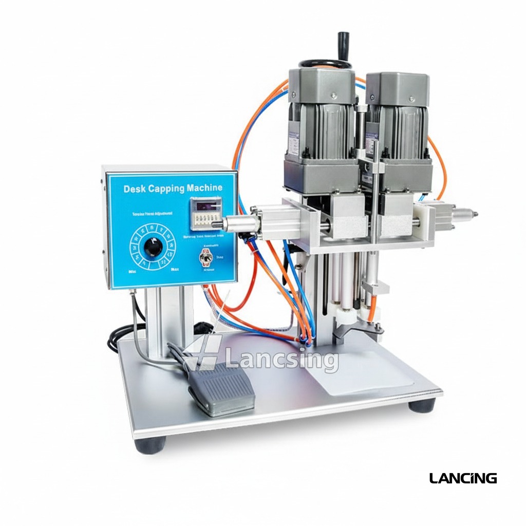
A compact pneumatic capping machine for operators who manually place pump closures and need faster, more repeatable tightening than hand capping.
Pump capping performance is governed by the complete pack. Bottle support, dip-tube insertion, pump-head orientation and thread engagement are developed together, using approved samples and a documented production requirement.
Project specification
The final specification is developed from approved bottle and pump samples, required output, line interfaces, site standards and documented acceptance criteria.
All performance and dimensions are indicative. Exact configuration and output are subject to approved samples, product information, agreed trials and final quotation.
| Configuration | Bench-mounted semi-automatic pump capping station |
|---|---|
| Output basis | Operator- and format-dependent; confirmed by sample trial |
| Closure compatibility | Configured to approved pump samples and tooling |
| Bottle compatibility | Configured to approved bottle samples and support tooling |
| Electrical requirements | Confirmed for the final controls and drive arrangement |
| Pneumatic requirements | Confirmed for the selected pneumatic tooling |
| Footprint | Confirmed on the approved equipment technical file |
Operating sequence
The final sequence is tailored to the selected closure feeder, bottle format and upstream/downstream interfaces.
The operator fills the bottle or receives it from the upstream process.
The operator inserts the dip tube and starts the pump on the bottle thread.
The container is located under the capping head.
The machine tightens the pump using the set cycle.
The operator removes the capped bottle and checks presentation.
Sample-led engineering
Reliable pump automation is proven with representative components rather than inferred from nominal dimensions.
Every size and shape, ideally decorated and at representative filled weight.
Production closures showing normal tube length, curvature, packing and batch variation.
Required sustained rate, shift pattern, batch size and expected line efficiency.
Torque, height, direction, leakage, cosmetic and reject acceptance criteria.
Machine views
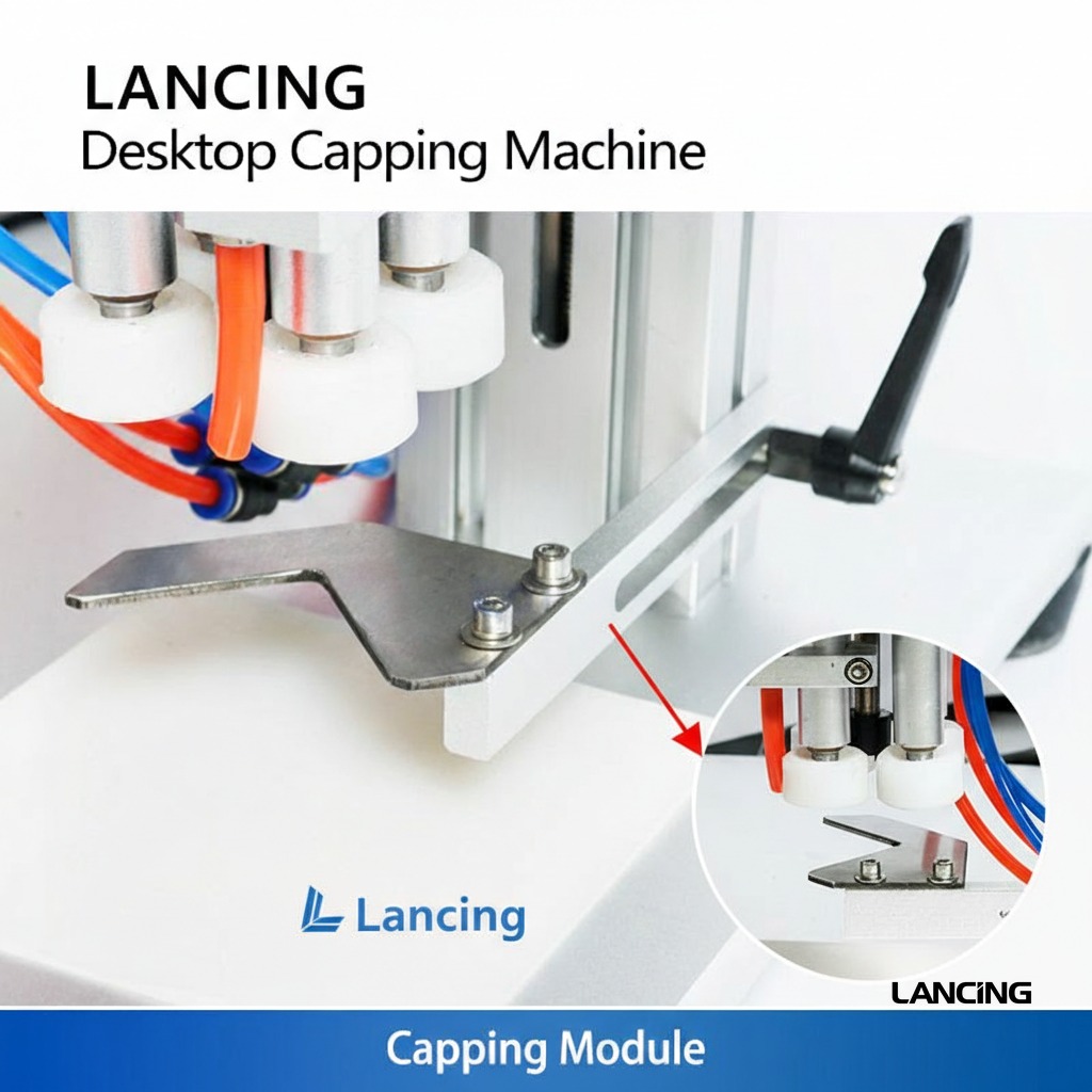
These real product photographs show representative equipment and process details. Your final configuration is confirmed against approved bottles, pumps and project requirements.
Practical answers
Every pump format behaves differently. Final machine selection and performance are confirmed through sample review and agreed trials.
Suitability depends on the complete bottle-and-pump combination, not only nominal diameter. Closure head shape, tube length and curvature, neck finish, filled weight and final presentation are reviewed before a configuration is confirmed.
Output is operator- and format-dependent and is confirmed by trial. Actual sustained output depends on the approved pack, feeding method, changeover, operator or line interfaces and agreed acceptance conditions. The project quotation states the tested or warranted basis.
Usually, provided each format falls within the engineered handling range. Some changes may be tool-free; others require guides, chucks, pockets, pump transfer parts or recipe changes. Supply the complete format matrix at enquiry stage.
The method depends on the closure. Directional actuators may be oriented in the feeder, during placement, by controlled thread engagement or in a separate orientation step. Exact directional tolerance must be agreed during testing.
Send representative bottles and pumps from normal production supply, including labelled or decorated bottles where marking is a concern. Filled-weight samples or safe ballast, component technical files and expected variation are also valuable.
Related machinery
Pump-cap feeding configuration
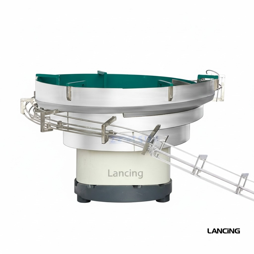
A dedicated machine for automatically presenting, picking and placing pump closures before a separate tightening station or integrated capping section.
View machine detailsConfigured inline system
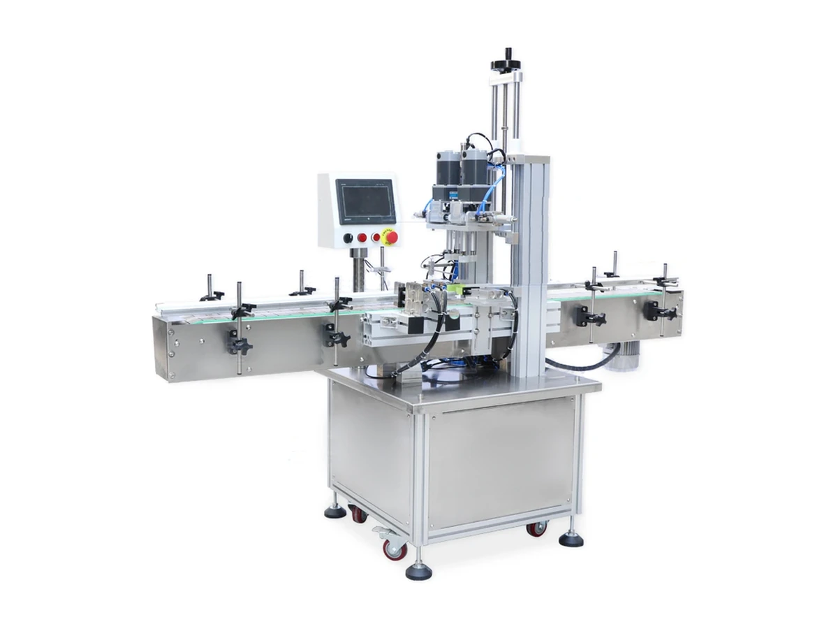
A flexible automatic screw-capping platform for suitable spray and pump closures, using in-line bottle control and powered capping modules.
View machine detailsCustom trigger sprayer capper
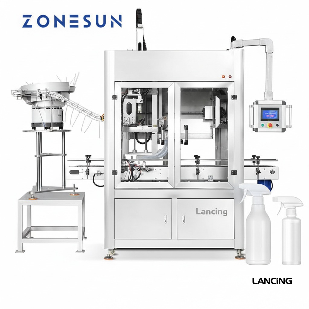
An automatic capping system engineered for trigger sprayers and dispenser pumps whose head shape, actuator direction and long dip tube require positive orientation and bottle control.
View machine detailsNext step
Send sample photographs, dimensions, planned formats and target output. Physical samples are used to confirm handling and the final machine specification.
Verified reference configuration
A compact semi-automatic capper can remove the variation of hand tightening while keeping pump placement manual. The operator sequence remains part of the production rate and quality result.
The first-party Lancing page publishes a working-speed range that depends on the bottle and cap. For pump closures, sustained output also depends on how consistently the operator picks up the pump, controls the tube, starts the collar and removes the completed bottle. A useful trial therefore uses the intended operator method, normal component presentation and a run length that exposes fatigue or tangling.
See the Lancing LU-XG6100 reference page for the published data. Final tooling, utilities and pump-capping performance must be confirmed for the approved samples.
The head must grip an approved drive surface without loading the actuator, unlocking the pump or marking a visible collar. A rigid chuck can suit a tightly controlled closure family; a compliant insert may protect decorative surfaces or accommodate minor variation. The selected insert, torque setting and bottle support should be treated as a controlled format set.
| Published Lancing reference | LU-XG6100 reference value |
|---|---|
| Machine model | LU-XG6100 |
| Working speed | 20–60 bottles/min, depending on bottle and cap |
| Bottle height | 100–300 mm |
| Cap diameter | 20–60 mm; custom maximum stated as 90 mm |
| Working voltage | AC 220 V / 110 V, 50–60 Hz |
| Power | 120 W |
| Machine size | 475 × 350 × 550 mm |
| Net weight | 28 kg |
The published range is not a guaranteed pump-capping rate. Agree the rate with the approved bottle, pump, tooling and operator sequence.
Daily operation
A semi-automatic machine performs best when the operator has a stable presentation method, clear first-off checks and a simple format-change routine.
Present pumps in a consistent orientation with enough space to prevent tubes tangling. The bottle nest or support should locate the neck beneath the head without the operator correcting alignment during the cycle. Tall, light or flexible bottles may need side support so the capping force does not tilt or deform the container.
At batch start, confirm the correct chuck, bottle support and setting. Approve closure height, actuator direction where relevant, cosmetic condition and the agreed torque or removal-torque method. Repeat the check after adjustment, component batch change, prolonged stop or any sign of inconsistent thread engagement.
Identify chucks, inserts, nests and settings by format. Clean grip surfaces and bottle supports so residue does not change friction or mark components. Inspect compliant inserts for wear, confirm the head runs concentrically and check that the foot switch or cycle control cannot be activated while the operator is repositioning a bottle.
Move beyond semi-automatic tightening when manual insertion limits sustained output, several operators are required, or inconsistent thread starts remain the main quality risk. The automation comparison guide provides a broader decision framework, while the automatic inline pump capper adds controlled pump transfer and placement.
Project review
Send the bottle, pump, batch size and desired rate so the required chuck, bottle support and trial conditions can be defined.
Controlled workstation
Repeatability depends on how pumps are staged, how bottles are located, how the operator starts the thread and how the finished pack is checked. The powered cycle is only one part of the method.
| Workstation step | Method to define | Acceptance observation |
|---|---|---|
| Pump presentation | How the operator selects, holds and inserts the pump without contaminating or damaging the actuator. | Tubes enter cleanly and the pump sits squarely before the powered cycle. |
| Bottle location | Base, neck or side support suited to the real filled weight and bottle geometry. | The bottle cannot lean, rotate or collapse as the closure is engaged. |
| Initial thread start | Operator cue or tooling feature used to avoid cross-threading before tightening. | The collar begins squarely on every approved neck finish. |
| Chuck or head engagement | Approved contact area, cycle setting and clearance from decorative surfaces. | No slipping, actuator damage, collar marking or unstable bottle movement. |
| First-off approval | Checks after setup or changeover for height, orientation, thread engagement, leakage and the agreed torque method. | Production does not begin until the format-specific sample is accepted. |
| Routine quality sampling | Frequency, sample size, measurement tool and reaction plan for a failed result. | Process drift is identified before a complete batch is affected. |
A semi-automatic machine can suit short campaigns and frequent changes because pump feeding and placement remain manual. That flexibility is valuable only when the operator can present components safely and consistently for the planned batch length. Trial the normal shift pattern rather than assuming a short demonstration represents a full production day.
Record the chuck or head, bottle support, height setting, cycle parameters and first-off checks for each format. Identify change parts clearly and store them to avoid damage. When a bottle, pump or tube revision changes, review whether the previous setup evidence still applies.
Agree how the pump is picked up, inserted, pre-threaded and released. Check reach, presentation height, component staging and the number of movements per cycle. The aim is not to publish an unsupported output figure; it is to establish a repeatable method that can be measured with the intended operator and pack.
Automatic placement becomes more relevant when manual insertion limits sustained output, creates repeated tube-entry faults or requires too much operator attention. Compare the observed batch method with the automatic inline pump capper and use the semi-automatic versus automatic guide to assess labour, format stability and integration rather than choosing from purchase price alone.
Batch trial
Send the format range, batch sizes, pump presentation method and quality checks so the workstation and tooling can be reviewed together.
Workstation planning
A semi-automatic capper can suit short runs and frequent format changes when the operator can place the dip tube cleanly, start the thread squarely and present the bottle consistently. The workstation should control component reach, bottle support, cycle initiation, completed-pack removal and the quality check without unnecessary handling.
Compare the tightening head using the chuck versus spindle or belt guide. Include realistic operator work in the output study and use the cost-factors guide when comparing this route with automatic feeding.
Operator-assisted questions
A semi-automatic pump capper is most useful when the manual placement task and the powered tightening cycle are designed as one repeatable workstation.
Powered tightening is useful when an operator can place the pump reliably but hand torque, cycle consistency or fatigue is limiting the process. The machine can standardise bottle support and the tightening motion while retaining flexibility for short batches and format changes.
The comparison should include real operator loading, first-off approval and quality sampling. A powered cycle is not automatically faster if tube placement remains awkward or the work area is poorly arranged.
Usually. The chuck or contact part must suit the pump collar or actuator without damaging it, and the bottle needs support that keeps the neck aligned during the cycle. Different formats may use adjusted guides, nests, chucks or height settings.
Tooling should be confirmed with production components, including decorated bottles and any actuator lock state that changes the available contact area.
Include collecting the pump, separating tangled components, inserting the dip tube, starting the collar where required, loading and unloading the bottle, initiating the cycle, inspecting the pack and placing rejects. Replenishment and minor recovery should also be included over a representative period.
This reveals whether the limiting step is the powered capper or the surrounding manual work and helps establish a realistic staffing plan.
Each approved bottle-and-pump combination should have identified tooling, settings and a first-off check. Where the machine has adjustable height, pressure or time, record the validated position or recipe rather than relying on operator memory.
A changeover should confirm the correct chuck, bottle support, alignment and finished-pack result before the batch starts. Formats outside the proven envelope should return to trial rather than borrowing settings from a similar pack.
Practical next step
Send the real pumps and bottles so tooling, ergonomics, cycle timing and first-off checks can be considered together.