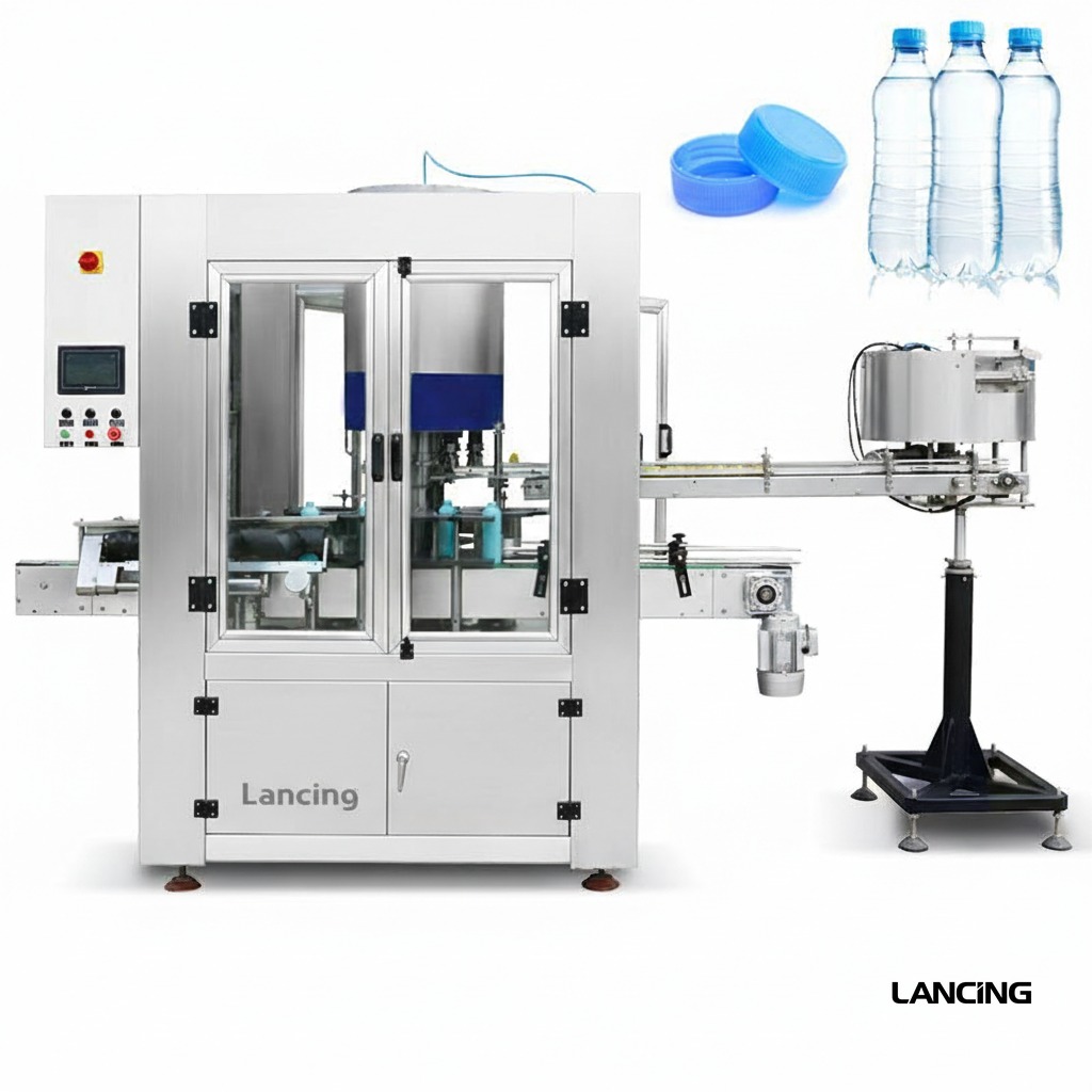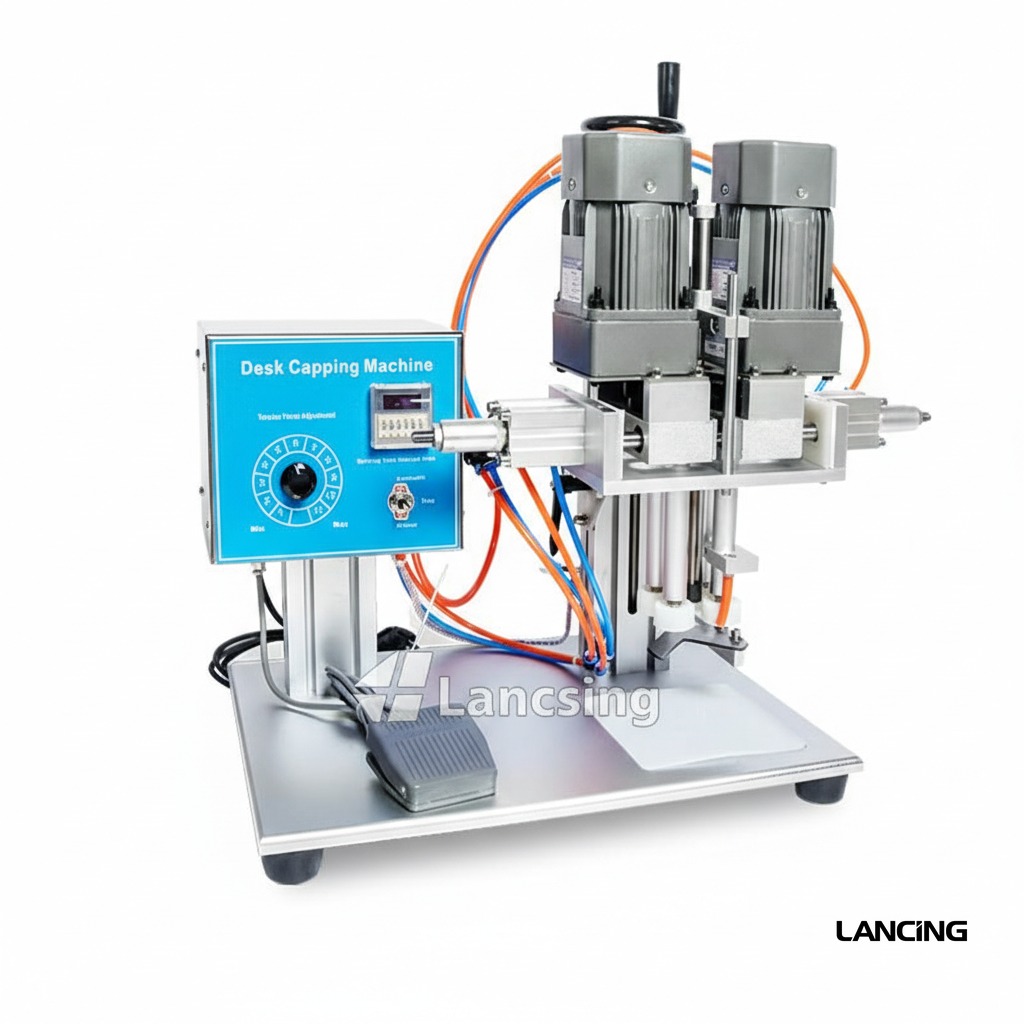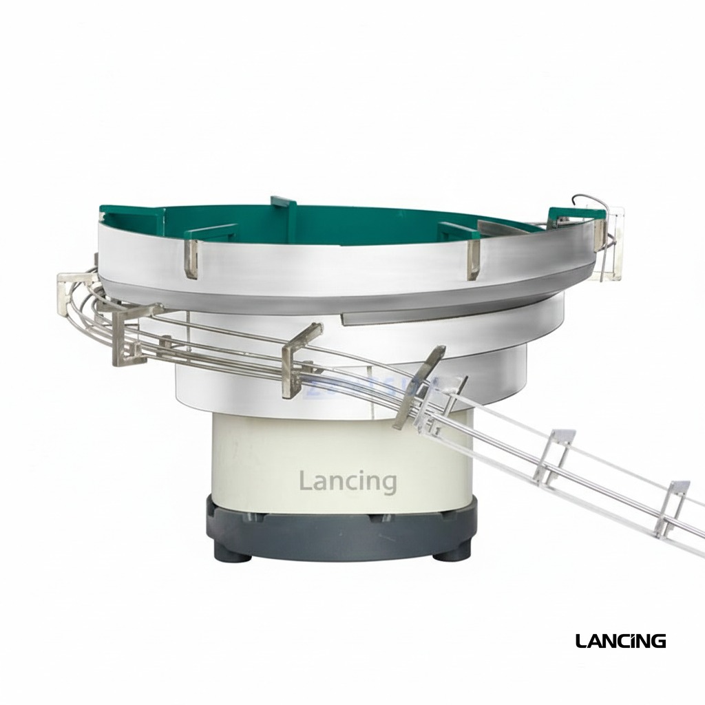
Bottle entry
Filled bottles are spaced and stabilised as they enter the capping section.
Inline pump capping
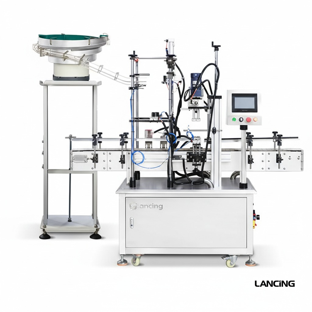
An automatic in-line system for placing and tightening pump closures, with bottle handling, closure transfer and powered capping in one compact production cell.
Where it fits
An automatic in-line system for placing and tightening pump closures, with bottle handling, closure transfer and powered capping in one compact production cell.
Pump capping performance is governed by the complete pack. Bottle support, dip-tube insertion, pump-head orientation and thread engagement are developed together, using approved samples and a documented production requirement.
Project specification
The final specification is developed from approved bottle and pump samples, required output, line interfaces, site standards and documented acceptance criteria.
All performance and dimensions are indicative. Exact configuration and output are subject to approved samples, product information, agreed trials and final quotation.
| Configuration | Automatic inline pump placement and tightening cell |
|---|---|
| Output basis | Confirmed by sample trial and agreed acceptance conditions |
| Closure compatibility | Configured to approved pump samples |
| Bottle compatibility | Configured to approved bottle samples |
| Electrical requirements | Confirmed for the final machine configuration |
| Pneumatic requirements | Confirmed after tooling and handling design |
| Footprint | Confirmed on the approved layout document |
Operating sequence
The final sequence is tailored to the selected closure feeder, bottle format and upstream/downstream interfaces.
Filled bottles are spaced and stabilised as they enter the capping section.
Pump closures are delivered in a controlled orientation for pickup or placement.
The dip tube is guided into the bottle and the closure is located on the neck finish.
Powered capping applies the configured pressure and torque.
Capped bottles leave the machine ready for inspection, labelling or packing.
Sample-led engineering
Reliable pump automation is proven with representative components rather than inferred from nominal dimensions.
Every size and shape, ideally decorated and at representative filled weight.
Production closures showing normal tube length, curvature, packing and batch variation.
Required sustained rate, shift pattern, batch size and expected line efficiency.
Torque, height, direction, leakage, cosmetic and reject acceptance criteria.
Machine views
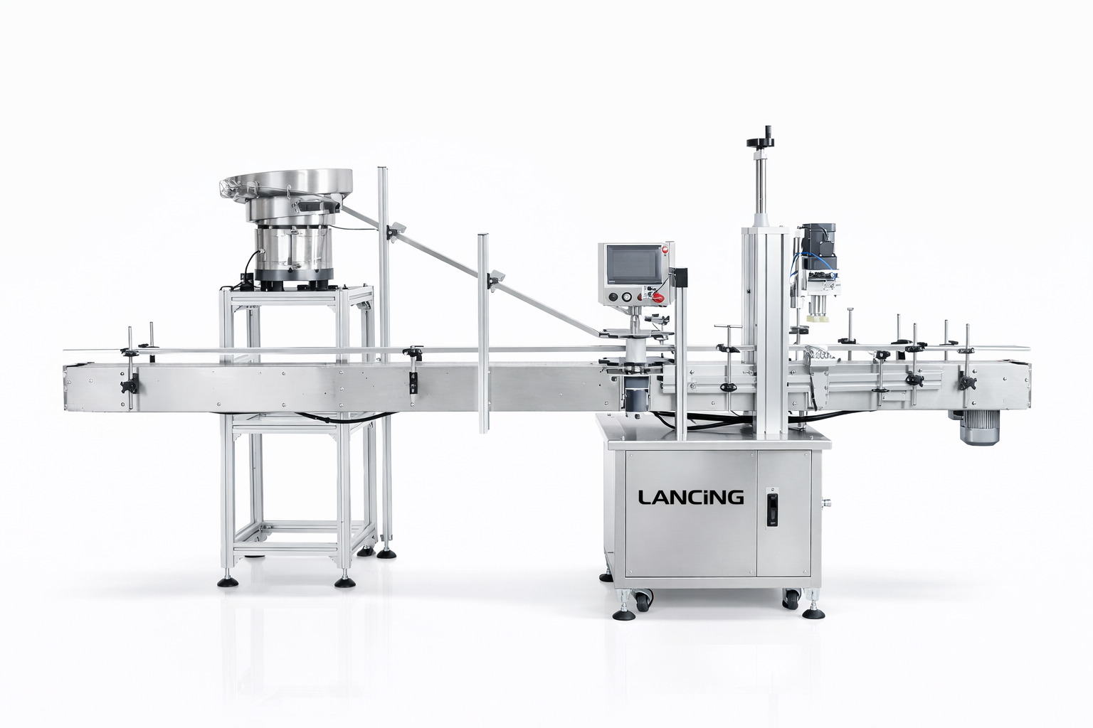
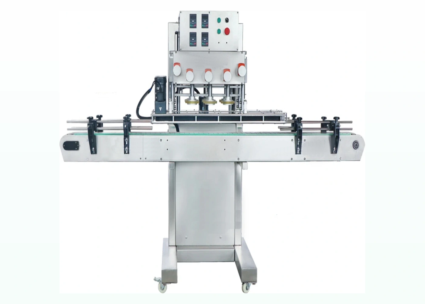
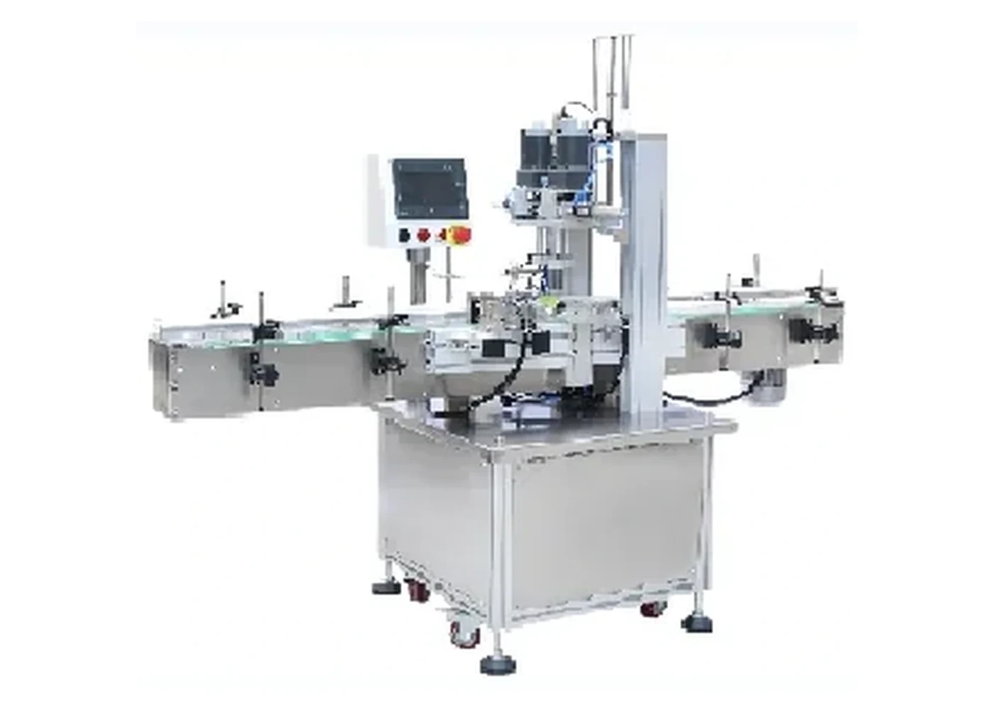
These real product photographs show representative equipment and process details. Your final configuration is confirmed against approved bottles, pumps and project requirements.
Practical answers
Every pump format behaves differently. Final machine selection and performance are confirmed through sample review and agreed trials.
Suitability depends on the complete bottle-and-pump combination, not only nominal diameter. Closure head shape, tube length and curvature, neck finish, filled weight and final presentation are reviewed before a configuration is confirmed.
Output is confirmed by sample trial. Actual sustained output depends on the approved pack, feeding method, changeover, operator or line interfaces and agreed acceptance conditions. The project quotation states the tested or warranted basis.
Usually, provided each format falls within the engineered handling range. Some changes may be tool-free; others require guides, chucks, pockets, pump transfer parts or recipe changes. Supply the complete format matrix at enquiry stage.
The method depends on the closure. Directional actuators may be oriented in the feeder, during placement, by controlled thread engagement or in a separate orientation step. Exact directional tolerance must be agreed during testing.
Send representative bottles and pumps from normal production supply, including labelled or decorated bottles where marking is a concern. Filled-weight samples or safe ballast, component technical files and expected variation are also valuable.
Related machinery
High-throughput rotary configuration
A custom rotary platform for high-volume pump bottle production where controlled transfer, repeatable closure placement and continuous output are critical.
View machine detailsSemi-automatic configuration
A compact pneumatic capping machine for operators who manually place pump closures and need faster, more repeatable tightening than hand capping.
View machine detailsPump-cap feeding configuration
A dedicated machine for automatically presenting, picking and placing pump closures before a separate tightening station or integrated capping section.
View machine detailsNext step
Send sample photographs, dimensions, planned formats and target output. Physical samples are used to confirm handling and the final machine specification.
Verified reference configuration
The figures below are published by Lancing for the reference machine. They describe a configurable platform, not an automatic guarantee for every pump, bottle or production condition.
The published range helps establish whether a sample review is worthwhile and which utilities and footprint may be relevant. It does not establish that every pump inside the stated diameter range will feed, insert or tighten reliably. Final performance depends on actuator geometry, collar drive surface, dip-tube behaviour, bottle neck and stability, component supply and the agreed run conditions.
See the Lancing LU-XG440I reference page for the first-party published machine data. The project quotation and sample trial remain the controlling documents for the supplied configuration.
A pump should enter the neck with the tube controlled and the collar square to the thread. Where the closure must be pre-threaded before powered tightening, the transfer should allow enough compliance to find the thread without forcing a cross-thread. The final capping head may use an approved chuck, roller or other drive surface depending on the collar and the permitted cosmetic contact. The head should not load the actuator or damage a locked pump position.
| Published Lancing reference | LU-XG440I reference value |
|---|---|
| Machine model | LU-XG440I |
| Working capacity | 10–25 bottles/min |
| Suitable cap size | About 20–60 mm |
| Suitable bottle diameter | About 25–100 mm |
| Suitable bottle height | About 100–300 mm |
| Voltage / power | 110/220 V, 450 W |
| Air pressure | About 0.4–0.6 MPa |
| Machine size | About 1950 × 620 × 1850 mm |
Capacity, component range, tooling and utilities must be confirmed against the approved bottles, pumps and acceptance method.
Line reliability
Usable output depends on maintaining control from bulk pump supply through placement and final discharge, including normal faults and format changes.
The feeder should provide pumps at a rate that supports the capper without uncontrolled accumulation. Define the demand signal, low-level warning, pump-present confirmation and what happens when the capper stops. The transfer should retain actuator orientation and prevent a long tube from catching on guides, adjacent pumps or the bottle shoulder.
Test missing bottles, missing pumps, a caught tube and a blocked transfer under controlled conditions. The machine should stop in a defined state, identify the affected zone and prevent the next pump from being placed onto an absent or mispositioned bottle. After clearance, restart should preserve the relationship between bottle and pump rather than relying on manual guesswork.
List every guide, nest, chuck, feeder rail, sensor position and recipe that changes. Mark settings and format parts so the approved condition can be restored. Product contact is normally limited, but pumps or bottles may carry residue; access should allow visible surfaces, grip inserts and guides to be inspected and cleaned without losing reference settings.
Confirm conveyor height, bottle pitch, accumulation, filler discharge, inspection, coding and labelling interfaces. A capper cannot sustain its tested rate if bottles arrive in unstable surges or if downstream equipment repeatedly blocks. The acceptance run should identify which equipment controls line speed and how stops are communicated.
Project review
Send representative bottles, pumps, dip-tube dimensions, target output and line layout so the LU-XG440I route can be assessed against the complete process.
Control sequence
A reliable automatic cell needs a controlled response when pumps or bottles are missing, a transfer is blocked or the downstream line stops. The sequence should protect the bottle-and-pump pairing and restart from a known condition.
| Process state | Control or evidence to define | What to observe during acceptance |
|---|---|---|
| Bottle available | Bottle-present detection, spacing and the point at which a bottle is committed to the capping cycle. | No empty cycle, double feed or bottle released without the intended pump status. |
| Pump ready | Feeder demand, pump-present confirmation and buffer condition before placement. | The capper waits or stops in a controlled way rather than sending an uncapped bottle through the cell. |
| Dip-tube insertion | Placement path, bottle location and a method for identifying a pump that has not seated correctly. | The longest and most curved approved tubes enter without folding, catching or pushing the pump off square. |
| Pre-threading or initial engagement | The motion that starts the closure squarely before final torque is applied. | No cross-threading, collar tilt or unstable bottle movement on the approved samples. |
| Tightening complete | Cycle completion signal and the quality characteristics checked by the process or sampling plan. | Closure height, orientation, torque method, leakage and cosmetic condition meet the agreed criteria. |
| Downstream blocked | Accumulation limit, stop signal and the state retained for bottles and pumps inside the cell. | No uncontrolled discharge, duplicate placement or loss of sequence when the downstream line restarts. |
| Fault recovery | Zone identification, safe clearance and restart logic after a missed pump, caught tube or stalled bottle. | The operator can remove the affected component and restart without creating a mismatched pack. |
The published LU-XG440I reference gives a starting capacity range, but the accepted production rate must be tied to the approved bottle, pump, feeder route and test conditions already described on this page. Record normal replenishment, operator tasks, deliberate stops and every intervention during the agreed run. A short cycle demonstration should not be treated as evidence of stable line output.
Record conveyor height and direction, bottle pitch, upstream release, downstream blocked signal, emergency-stop interface, reject destination and responsibility for each transfer point. Where separate suppliers provide the filler, feeder, capper or labeller, identify which controller owns the line state and how a fault is exchanged.
After changeover, check the correct guides, bottle support, placement tooling, capping head and recipe before normal running. Inspect a defined first-off sample for tube insertion, thread engagement, closure height, actuator condition, cosmetic contact and the approved torque or removal-torque method. Keep settings and change parts traceable to the exact component revision.
Introduce a controlled missing pump, mis-presented pump, stalled bottle and downstream block. Confirm the alarm, stop state, clearance method and restart. Link the observations to the pump capping troubleshooting guide so the handover includes practical fault boundaries rather than only steady-running footage.
Inline project review
Send the line layout, format matrix, pump packing and acceptance priorities so placement, tightening and integration can be reviewed together.
Automatic-line definition
An inline pump capper must receive bottles at controlled spacing, obtain a pump from the feeder, guide the dip tube into the neck, establish square thread engagement, tighten the closure and release an accepted pack. Define ready, demand, blocked and fault behaviour at the upstream and downstream boundaries.
Use the line-integration guide to prepare the interface schedule and the capacity guide to define sustained accepted output. The trial should include normal replenishment, a controlled pump misfeed, downstream blockage and restart where safe and relevant.
Automatic line questions
The automatic sequence should prove that a correctly presented pump and a correctly positioned bottle are available before irreversible movement begins.
The system should confirm that a bottle is present in the intended position, the placement station is ready, a correctly presented pump is available and downstream conditions allow the cycle to complete. The exact sensing method depends on the approved machine design and component geometry.
Those confirmations should prevent a pump being released into an empty station, a second pump entering an occupied transfer or a bottle moving before tube insertion is complete.
A missing or misfed pump should produce a controlled state rather than an uncontrolled retry. The line may stop, reject the affected bottle or hold the sequence, depending on where the fault is detected and whether the component can be recovered safely.
The acceptance plan should define fault indication, component disposition, reset authority and the condition required before restart. Repeated automatic cycling against a misplaced pump can damage the pack or obscure the original cause.
Final torque cannot reliably correct a pump collar that entered the neck thread at an angle. If the thread start is skewed, extra tightening can damage threads, distort the closure or create a bottle that feels tight but is not seated correctly.
Placement height, bottle location, initial engagement and closure support should therefore be proved before the final chuck, spindle or belt stage is tuned.
The run should demonstrate approved formats under representative supply conditions, including pump replenishment, tube variation, bottle flow, normal operator work, defined quality sampling and controlled stop-and-restart behaviour. Record interventions and rejected packs by cause.
It should also show how the line responds to a missing bottle, unavailable pump and downstream blockage where those tests are safe and included in the agreed scope.
Practical next step
A useful trial records what happens when everything is correct and how the machine returns to a known state after a controlled fault.
Finished-pack control
An automatic inline pump capper should have a defined result for every indexed bottle. Decide which conditions are checked at the capping station, which are checked downstream and how the control system prevents a failed or unprocessed pack entering the saleable flow.
Inspection may confirm pump presence, closure height, actuator direction or another visible condition, but the selected method must match the actual defect risk. Sample-based torque, leakage or functional checks can then support the non-destructive line checks. The inspection and reject guide provides a selection framework.
Guarding must also cover the feeder handover, bottle transfer, placement motion and tightening head, while allowing planned replenishment, cleaning, changeover and controlled recovery. Use the safety and guarding guide to define the information needed for the project review.
Format boundary
An inline pump capper can control feeding, placement and tightening, but the complete cell still has to suit the bottle body, finished seal and any overcap station.
Specify guides, side belts, pucks or fixtures around the actual PET, HDPE or glass bottle at representative filled weight.
Define how thread start, seal condition, product contamination and distribution testing will be assessed rather than relying on torque alone.
Decide whether an overcap remains on the pump or needs a separate feed, application, inspection and reject station.