Pump capping machine range

Compare pump capping machines for your production target.

See where each machine type fits, from operator-assisted tightening to automatic pump feeding and high-output integrated lines.

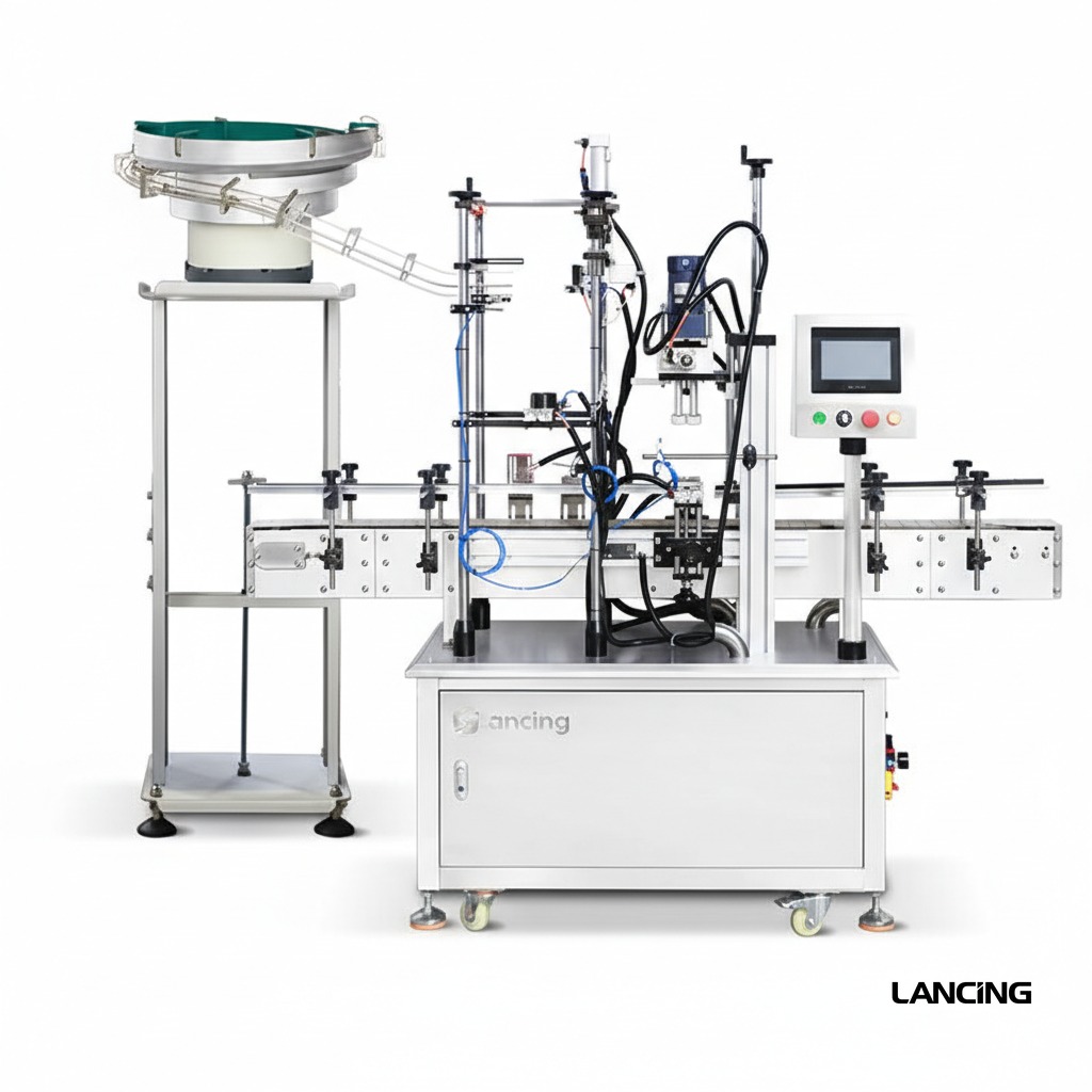
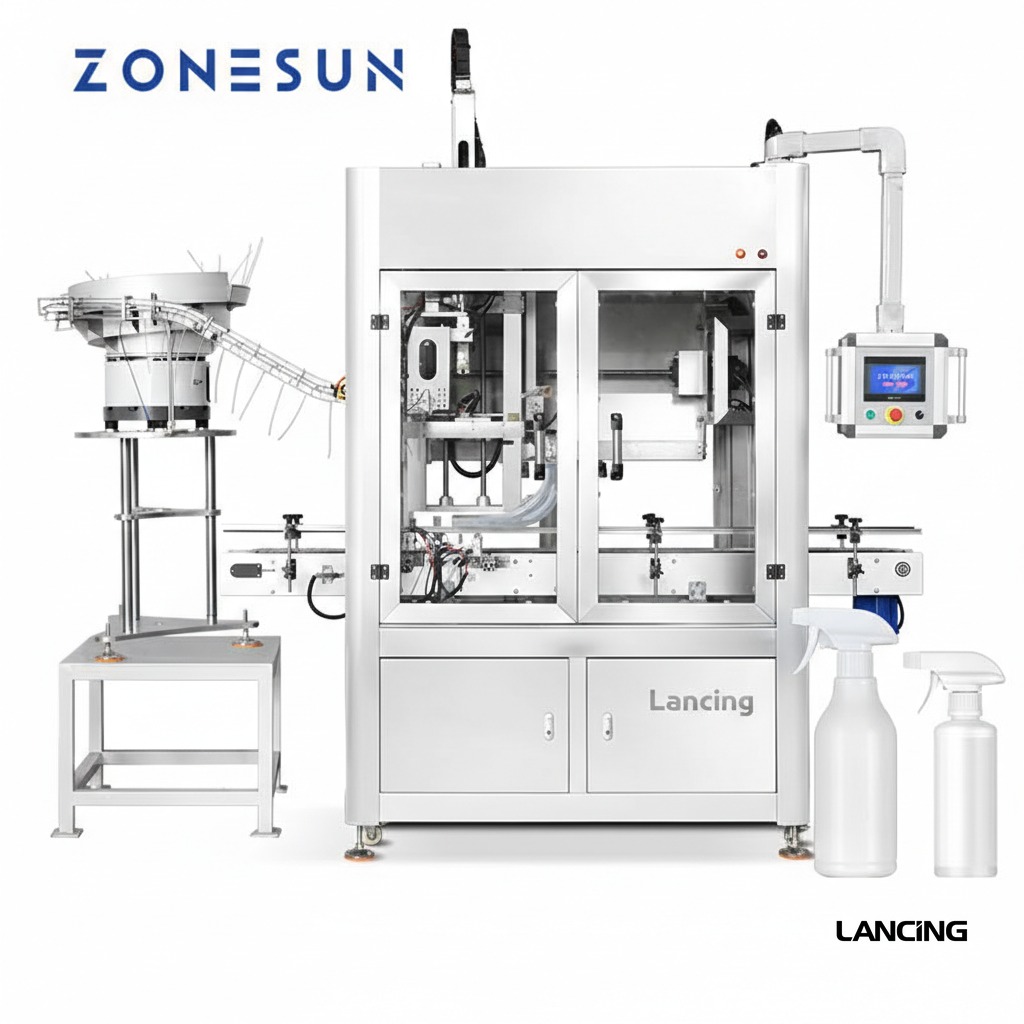
Automatic pump closure feeding and placement machineFeeding · placement · tightening

Seven configurations

Shortlist by your production process, not cap diameter alone.

A useful specification starts with pump geometry, tube behaviour, bottle stability, output and presentation requirements. The listed ranges are indicative and subject to approved sample testing.

Automatic inline configuration

Automatic inline pump capper

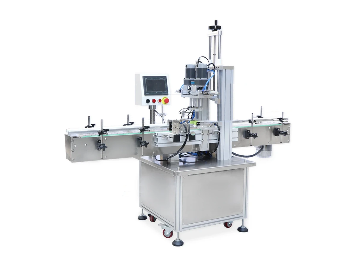
An automatic in-line system for placing and tightening pump closures, with bottle handling, closure transfer and powered capping in one compact production cell.

Output
Confirmed by sample trial
Best for
Growing production lines that need consistent pump placement and repeatable tightening.
View machine details

High-throughput rotary configuration

High-speed rotary capper

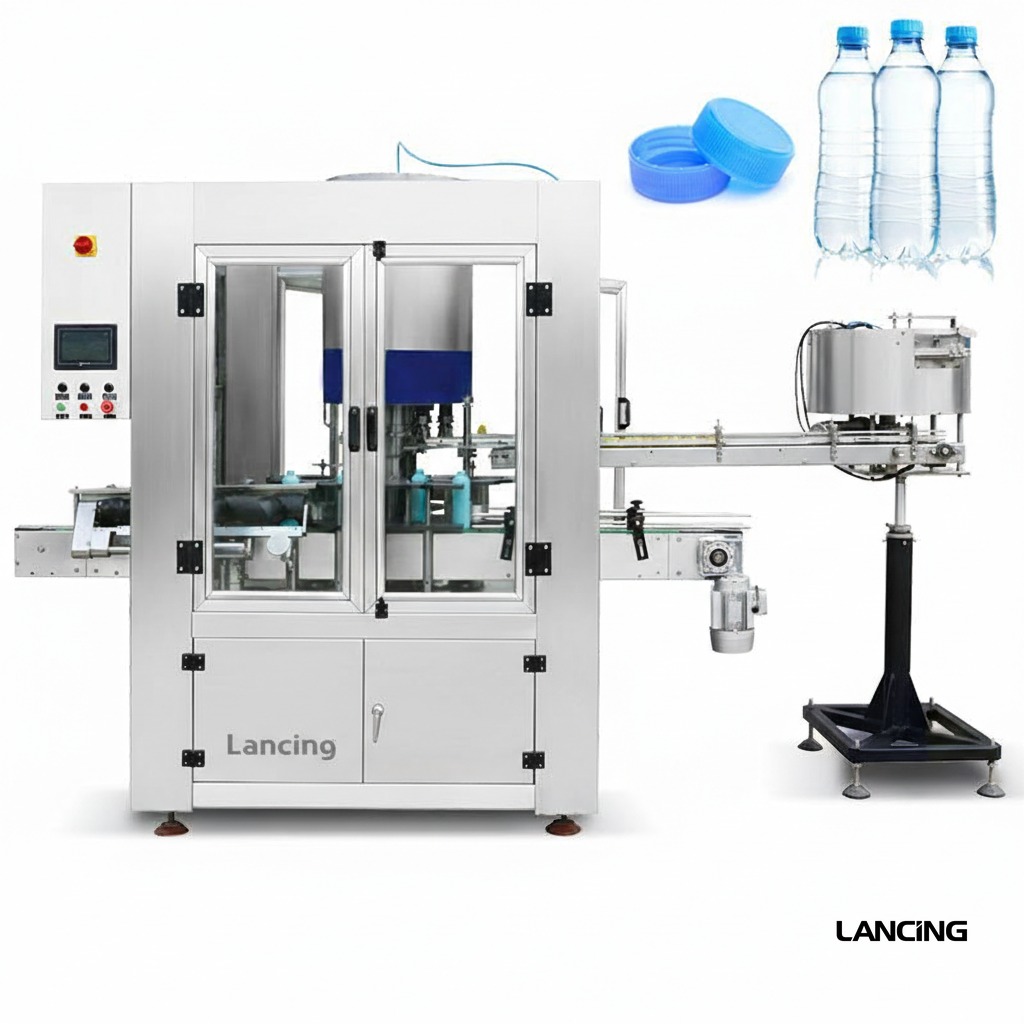
A custom rotary platform for high-volume pump bottle production where controlled transfer, repeatable closure placement and continuous output are critical.

Output
Configured for sustained high-throughput production
Best for
Large, stable product runs and production environments targeting multi-thousand-bottle hourly output.
View machine details

Semi-automatic configuration

Semi-automatic pump capper

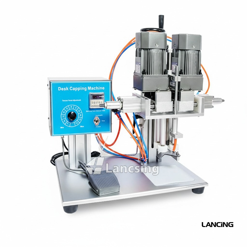
A compact pneumatic capping machine for operators who manually place pump closures and need faster, more repeatable tightening than hand capping.

Output
Operator- and format-dependent; confirmed by trial
Best for
Start-ups, short runs, frequent format changes, laboratories and lower-volume production.
View machine details

Pump-cap feeding configuration

Pump cap feeding machine

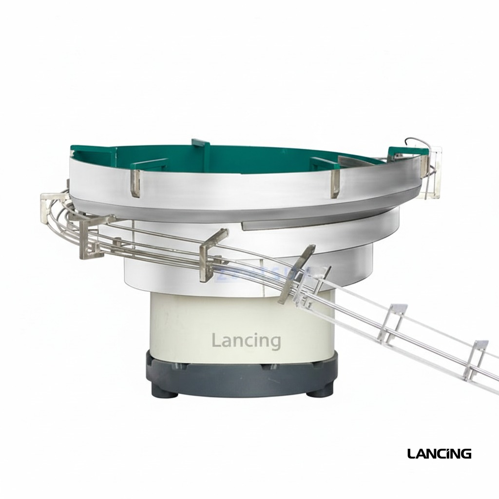
A dedicated machine for automatically presenting, picking and placing pump closures before a separate tightening station or integrated capping section.

Output
Matched to the downstream capping rate
Best for
Lines where long dip tubes and asymmetric pump heads make closure feeding the principal automation challenge.
View machine details

Configured inline system

Spray and pump screw capper

A flexible automatic screw-capping platform for suitable spray and pump closures, using in-line bottle control and powered capping modules.

Output
Confirmed by sample trial
Best for
Mixed-format production where a validated inline capping platform can serve suitable pump, spray and conventional screw closures.
View machine details

Custom trigger sprayer capper

Trigger and dispenser pump capper

An automatic capping system engineered for trigger sprayers and dispenser pumps whose head shape, actuator direction and long dip tube require positive orientation and bottle control.

Output
Configured to sample behaviour and required line rate
Best for
Household, automotive, garden, chemical and personal-care products using trigger or directional dispenser closures.
View machine details

Guarded automatic configuration

Enclosed automatic capper

A guarded automatic capping platform that can be assessed for pump-compatible applications where enclosure, controlled access and an integrated production-cell format are required.

Output
Confirmed by sample trial
Best for
Production areas seeking a guarded machine format, subject to successful pump feeding, placement and sample trials.
View machine details

At-a-glance comparison

Shortlist a machine architecture.

Output depends on the complete pack, feeding method, operator or line interfaces and agreed acceptance conditions. Final performance is documented in the project proposal.

Comparison of pump capping machine configurations
MachineIndicative outputClosure rangeTypical use
Automatic inline pump capperConfirmed by sample trialConfigured to approved closure samplesGrowing production lines that need consistent pump placement and repeatable tightening.
High-speed rotary capperConfigured for sustained high-throughput productionCustom to approved pump samplesLarge, stable product runs and production environments targeting multi-thousand-bottle hourly output.
Semi-automatic pump capperOperator- and format-dependent; confirmed by trialConfigured to approved closure samplesStart-ups, short runs, frequent format changes, laboratories and lower-volume production.
Pump cap feeding machineMatched to the downstream capping rateCustom to approved samplesLines where long dip tubes and asymmetric pump heads make closure feeding the principal automation challenge.
Spray and pump screw capperConfirmed by sample trialConfigured to approved closure samplesMixed-format production where a validated inline capping platform can serve suitable pump, spray and conventional screw closures.
Trigger and dispenser pump capperConfigured to sample behaviour and required line rateCustom to approved trigger or pump samplesHousehold, automotive, garden, chemical and personal-care products using trigger or directional dispenser closures.
Enclosed automatic capperConfirmed by sample trialConfigured to approved closure samplesProduction areas seeking a guarded machine format, subject to successful pump feeding, placement and sample trials.
01

Manual pump placement

Use semi-automatic tightening where batches are short, formats change often or an operator can comfortably maintain the required output.

View semi-automatic capper
02

Automatic placement

Add pump feeding and insertion where labour, consistency or sustained output justifies a format-specific closure handling system.

View pump feeding machine
03

Integrated high output

Use an inline or rotary platform for stable, higher-volume programmes with defined pack formats and acceptance criteria.

View high-speed capper

Next step

Need help shortlisting the machine type?

Send the bottle, pump, target output and current process. We will identify the likely automation level and the samples needed for validation.

Machine architecture

Choose the architecture around the hardest handling step.

Pump capping projects are easier to compare when feeding, placement, insertion and tightening are treated as separate functions rather than one generic machine label.

Pump capping machine architecture comparison
Machine routeWhere it adds valueEvidence to confirm
Semi-automatic tighteningThe operator presents the pump and the machine applies a controlled tightening cycle.Operator method, chuck contact, bottle support, cycle time and in-process quality checks.
Automatic inline pump capperPumps are transferred, inserted and tightened as bottles pass through an inline cell.Pump presentation, handover timing, tube entry, thread start, bottle control and restart behaviour.
Separate pump feederA dedicated system separates and presents pumps to the downstream placement or capping process.Bulk packing, tangling behaviour, orientation, buffer logic, demand signals and jam recovery.
High-output rotary capperStarwheel and turret handling support high sustained output for controlled formats.Component consistency, transfer stability, turret tooling, line balance, inspection and formal FAT conditions.
Mixed pump/screw platformA validated inline platform serves selected pump, spray and conventional screw closures.A format matrix proving which head, belt, chuck, guide and feeding method applies to each closure.
Enclosed automatic cellGuarded access and integrated controls are required around automatic handling.Operator tasks, line interfaces, fault clearance, reject containment, changeover and project-specific risk controls.

Separate feeding from tightening.

A pump can tighten correctly once it is on the thread yet still be unsuitable for automatic feeding. Long tubes may cross, knot or retain a set from bulk packing. An actuator may be easy to grip but difficult to orient. A tall bottle may accept the cap but become unstable during transfer. Assessing each stage prevents a strong capping head from being paired with an unreliable presentation method.

Keep related closure intents in the right place

This website owns the pump-closure decision: lotion pumps, dispenser pumps, spray pumps, long dip tubes and the machinery that places and tightens them. For a trigger-sprayer-only project, use the dedicated trigger capping route. For standard screw-cap belt and spindle systems, use Spindle Cappers UK. For feeder-only selection, use Cap Feeders UK. This keeps the enquiry focused without creating competing pages for the same specialist intent.

Compare machines on one acceptance basis

Ask each proposed route to demonstrate the same approved formats, sustained run conditions and quality checks. Record replenishment, normal stops, fault recovery and changeover as well as steady running. A lower nominal cycle rate may deliver better usable output when it is easier to replenish, recover and change over.

Project review

Shortlist the machine by feeding, insertion and tightening risk.

Share the complete format matrix and required output so the machine architecture can be compared against the real pack.

Machine comparison

Compare the complete pump-handling route, not only the capping head.

Each architecture divides the work differently between the operator, feeder, transfer system, bottle handling and tightening station. The best shortlist reflects the hardest format and the way production is actually run.

Comparison of pump capping machine architectures
RoutePump placementProject conditions that support the routeCritical trial evidence
Semi-automatic pump capperManual placement before a powered tightening cycle.Short or varied batches, manageable operator loading and formats that can be placed squarely by hand.Operator method, chuck contact, bottle support, first-off approval and sustained batch rhythm.
Automatic inline pump capperAutomatic or controlled transfer into an inline placement and tightening sequence.Repeatable bottle supply, stable format families and a production case for reduced manual placement.Tube insertion, pre-threading, feeder/capper handover, line signals, stop recovery and sustained output.
Separate pump feeder and placement moduleBulk separation, orientation and transfer are developed as a dedicated process.The closure is the principal automation risk or the downstream capper already exists.Normal bulk packing, pump variation, buffer control, placement accuracy and downstream demand response.
Enclosed automatic cellPlacement and tightening operate within a guarded machine boundary.The project needs defined access, integrated recovery and an enclosed production cell.Operator tasks, guarding interfaces, fault clearance, cleaning, maintenance and first-off restart.
Rotary or multi-head platformContinuous or indexed transfer through multiple controlled stations.Large stable runs and a defined format set that justify project-specific high-output engineering.Component control, infeed/outfeed transfer, intervention log, quality sampling and formal FAT conditions.

Keep the search route aligned with the closure problem.

This website is centred on lotion pumps, dispenser pumps and related long dip-tube closures where feeding, insertion, pre-threading, bottle stability and final presentation have to be considered together. That is different from selecting a general-purpose screw capper from cap diameter and bottle size alone.

Use the specialist trigger route for trigger-only projects

When every closure is a directional trigger sprayer and the project is driven by trigger orientation, tube control and spray-bottle presentation, Trigger Cappers UK provides the narrower specialist route. This site remains useful when trigger and lotion-pump formats must be compared within one pump-capping project.

Use the specialist spindle route when progressive tightening is the core requirement

For conventional threaded closures that are already placed on the bottle and need progressive belt or wheel tightening, refer to Spindle Cappers UK. A pump closure can use a spindle-style tightening stage only when placement, pre-threading and bottle control have first been proven.

Separate general cap feeding from pump-specific placement

Cap Feeders UK covers broad cap feeder, bowl, elevator, orientator and retrofit intent. The pump feeder page here focuses on asymmetric pump heads and dip tubes that must remain controlled through placement. For a broader comparison across screw caps, ROPP closures, pumps and triggers, use Bottle Cappers UK.
Shortlist review

Compare the machine routes against one approved format matrix.

Send the bottles, pumps, target output and current production method so the relevant architectures can be assessed on the same basis.

Architecture selection

Compare pump cappers by responsibility, not only by machine layout.

The key question is who or what places the pump, controls the tube, starts the thread, stabilises the bottle and verifies the finished pack.

Pump capping machine architecture selection
RouteBest assessed whenEvidence to obtain
Semi-automatic tighteningAn operator can place and start the pump, campaigns are shorter or formats change frequently.Repeatable operator sequence, head contact, bottle support, quality and realistic cycle study.
Automatic inline cappingComponents can be presented consistently and the line needs sustained automatic handling.Bulk pump feed, tube entry, pre-threading, tightening, replenishment and recovery.
Separate feeder and placerPump presentation is the main engineering risk or the downstream capper is defined separately.Feeder-level behaviour, escapement, handover, demand signals and controlled restart.
Rotary or multi-head platformThe complete pack, line balance and campaign length justify a more integrated architecture.Representative sustained run, changeover, reject route and line-interface evidence.
Enclosed automatic cellGuarded access, defined operator intervention and compact machine boundaries are priorities.Access, fault recovery, format handling, utilities and site layout review.

Machine selection questions

Questions that help separate pump placement, bottle control and final tightening.

A pump-capping line is easier to specify when the handling stage that limits the process is identified before a machine architecture is chosen.

Which stage should determine the pump-capper architecture?

The architecture should be driven by the stage that is hardest to make repeatable: separating pumps, orienting the actuator, inserting the dip tube, starting the thread, holding the bottle or applying the final tightening cycle. Selecting around nominal cap diameter alone can leave the true bottleneck unresolved.

Use sample observation to rank those risks. A separate feeder, operator-assisted station, inline cell or rotary platform can then be compared against the same acceptance conditions.

Is a separate pump feeder always required?

No. A semi-automatic capper can retain manual pump placement, and some automatic lines integrate feeding and placement within one guarded cell. A separate feeder is useful when bulk pump presentation is a distinct project boundary or must be matched to an existing tightening machine.

The decision depends on normal component packaging, tube behaviour, buffer requirements, available space and who owns the feeder-to-capper interface.

When does a rotary pump capper become a credible option?

A rotary or multi-head pump capper becomes credible when the approved formats, component supply and connected line can support stable repeated transfers at the required production rate. Higher nominal head count does not remove problems caused by tangled pumps, unstable bottles or uncontrolled thread starts.

The proposal should define the exact format set, transfer method, replenishment, reject handling, changeover and sustained acceptance run before rotary capacity is treated as usable output.

How should manual operator work be included when comparing machines?

Record every repeatable operator task: loading pumps, placing closures, replenishing a feeder, clearing accepted minor faults, sampling quality and changing formats. A machine cycle that excludes those tasks can overstate the output available from the actual production method.

Compare accepted packs per staffed hour, the physical sequence and the variation between operators. This can reveal when a controlled semi-automatic station is more practical than a partially automated line.

Browse the question libraryDiscuss your pump-capping project

Practical next step

Choose the architecture around the limiting operation, not the most impressive machine label.

Lancing can review the sample pack and identify whether the project is mainly a feeding, placement, tightening or bottle-handling problem.

Complete-cell scope

Include inspection, reject handling and safe access in the machine comparison.

Two cappers can use a similar tightening head but provide very different production control. Compare how each route confirms a bottle is present, prevents release without a pump, detects an incomplete cycle, identifies a failed pack and recovers after a controlled stop.

Also define where operators replenish pumps, change tooling, clean contact parts and clear faults. The required guarding and access strategy can affect the footprint and the practical changeover time, so it should be reviewed before the layout is frozen.

Plan inspection and rejectionPlan guarding and access
Call 01494 623015 Send project details