Format setup
Guides, head and handling components are set for the approved container.
Guarded capping cell
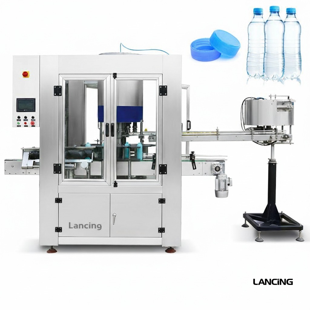
A guarded automatic capping platform that can be assessed for pump-compatible applications where enclosure, controlled access and an integrated production-cell format are required.

Where it fits
A guarded automatic capping platform that can be assessed for pump-compatible applications where enclosure, controlled access and an integrated production-cell format are required.
Pump capping performance is governed by the complete pack. Bottle support, dip-tube insertion, pump-head orientation and thread engagement are developed together, using approved samples and a documented production requirement.
Project specification
The final specification is developed from approved bottle and pump samples, required output, line interfaces, site standards and documented acceptance criteria.
All performance and dimensions are indicative. Exact configuration and output are subject to approved samples, product information, agreed trials and final quotation.
| Configuration | Guarded automatic pump-capping cell |
|---|---|
| Output basis | Confirmed by sample trial and agreed acceptance conditions |
| Closure compatibility | Configured to approved pump samples |
| Bottle compatibility | Configured to approved bottle samples |
| Electrical requirements | Confirmed for the final machine configuration |
| Pneumatic requirements | Confirmed after tooling and handling design |
| Footprint | Confirmed on the approved layout document |
Operating sequence
The final sequence is tailored to the selected closure feeder, bottle format and upstream/downstream interfaces.
Guides, head and handling components are set for the approved container.
A compatible manual or automatic method presents the pump to the bottle.
The container enters the guarded capping area.
The capping system applies the configured cycle.
The bottle exits the enclosure for downstream operations.
Sample-led engineering
Reliable pump automation is proven with representative components rather than inferred from nominal dimensions.
Every size and shape, ideally decorated and at representative filled weight.
Production closures showing normal tube length, curvature, packing and batch variation.
Required sustained rate, shift pattern, batch size and expected line efficiency.
Torque, height, direction, leakage, cosmetic and reject acceptance criteria.
Machine views
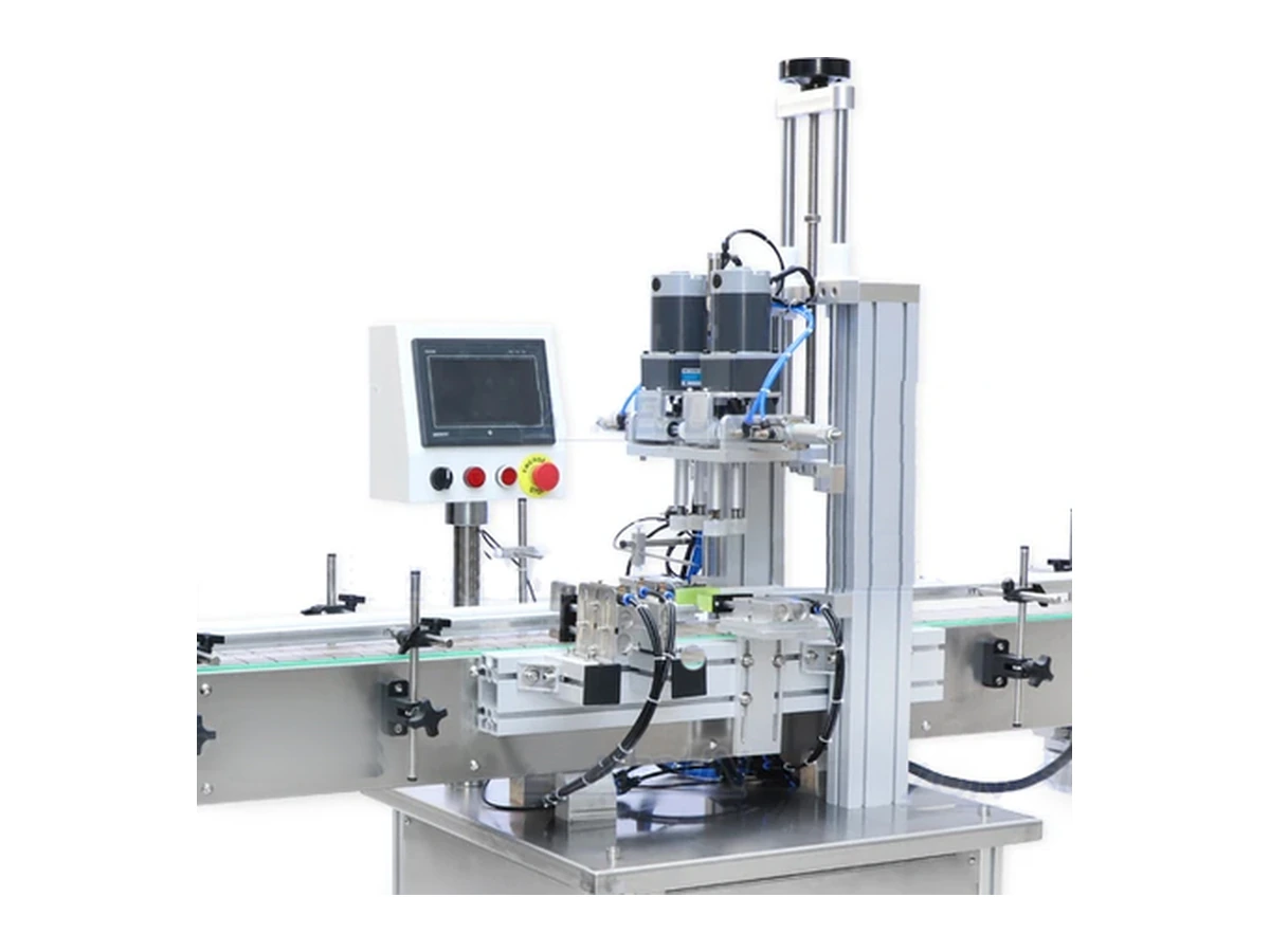
These real product photographs show representative equipment and process details. Your final configuration is confirmed against approved bottles, pumps and project requirements.
Practical answers
Every pump format behaves differently. Final machine selection and performance are confirmed through sample review and agreed trials.
Suitability depends on the complete bottle-and-pump combination, not only nominal diameter. Closure head shape, tube length and curvature, neck finish, filled weight and final presentation are reviewed before a configuration is confirmed.
Output is confirmed by sample trial. Actual sustained output depends on the approved pack, feeding method, changeover, operator or line interfaces and agreed acceptance conditions. The project quotation states the tested or warranted basis.
Usually, provided each format falls within the engineered handling range. Some changes may be tool-free; others require guides, chucks, pockets, pump transfer parts or recipe changes. Supply the complete format matrix at enquiry stage.
The method depends on the closure. Directional actuators may be oriented in the feeder, during placement, by controlled thread engagement or in a separate orientation step. Exact directional tolerance must be agreed during testing.
Send representative bottles and pumps from normal production supply, including labelled or decorated bottles where marking is a concern. Filled-weight samples or safe ballast, component technical files and expected variation are also valuable.
Related machinery
Automatic inline configuration
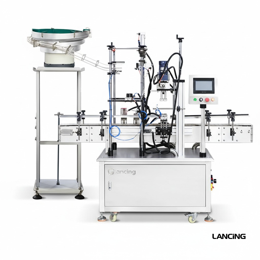
An automatic in-line system for placing and tightening pump closures, with bottle handling, closure transfer and powered capping in one compact production cell.
View machine detailsHigh-throughput rotary configuration
A custom rotary platform for high-volume pump bottle production where controlled transfer, repeatable closure placement and continuous output are critical.
View machine detailsSemi-automatic configuration
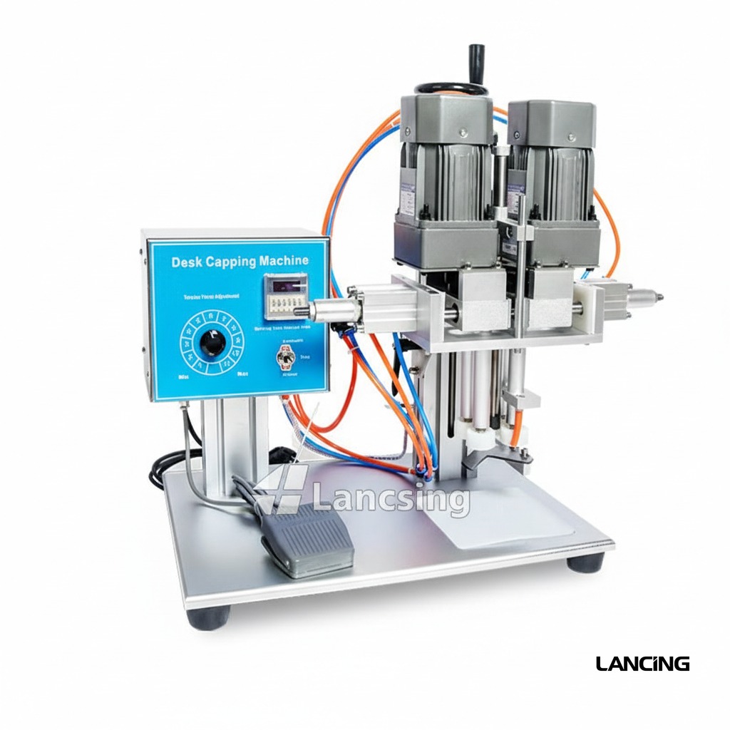
A compact pneumatic capping machine for operators who manually place pump closures and need faster, more repeatable tightening than hand capping.
View machine detailsNext step
Send sample photographs, dimensions, planned formats and target output. Physical samples are used to confirm handling and the final machine specification.
Guarded cell definition
An enclosure can support controlled access and integrated automation, but it does not replace the need to prove pump feeding, tube insertion, bottle support and tightening.
| Area to define | Project question | Evidence for the final specification |
|---|---|---|
| Operator access | Which tasks require routine access for loading, adjustment, inspection and cleaning? | Operator workflow, access frequency and component loading method. |
| Fault recovery | How will a caught pump, missed bottle or blocked transfer be made safe and cleared? | Fault scenarios, isolation sequence and restart method witnessed during trials. |
| Guarding interfaces | Where do conveyors, services and upstream/downstream equipment enter the cell? | Layout drawing, conveyor height, service points and responsibility boundaries. |
| Inspection and rejects | How are missing, high, misdirected or cross-threaded pumps detected and contained? | Acceptance limits, sensor concept, reject destination and line-stop logic. |
| Changeover | Which guarded areas must be opened and which parts or settings change? | Format-specific parts list, adjustment points and first-off approval checklist. |
| Maintenance | Which heads, drives, sensors and transfer parts need planned access? | Maintenance task list, access envelope, wear parts and safe service method. |
Identify how pumps are replenished, how bottles are sampled, where rejected components are removed and which adjustments are routine. Doors, access panels and control positions should support those tasks without encouraging operators to reach across the process or defeat guarding for normal production.
A guarded machine can lose significant time if a minor pump misfeed requires a complex reset. The trial should include controlled faults at the feeder, placement station and capping head. The operator should be able to identify the affected zone, make the process safe, remove the component and restart from a known sequence without creating another mismatched bottle and pump.
Review the routes used to remove trapped pumps, wipe sensors, clean guide surfaces and replace format parts. Long dip tubes can remain hidden below rails or transfer nests. Format components should be identifiable and stored to avoid damage. After changeover, the machine should support a controlled first-off inspection before normal running resumes.
The final guarding, interlocks, control system and risk-reduction measures must be developed for the supplied machine and its installation. This page does not claim a particular certification or performance level. Share site standards, adjacent machinery, operator tasks and the intended maintenance method before the final design is agreed.
Define who supplies conveyors, guarding extensions, service isolation, line control, upstream/downstream stop signals, product changeover and reject handling. The enclosure boundary should align with the actual machine scope and leave no ambiguous transfer point between separate suppliers.
Project review
Send the line layout, operator workflow, pump formats and site standards so access and interfaces can be considered with the capping process.
Guarded-cell planning
An enclosed automatic cell needs a clear operating boundary: normal loading and replenishment points, authorised access, safe recovery from a pump or bottle fault, format-change areas and the interface with adjacent conveyors. The actual machinery and site require a competent risk assessment and the supplier’s operating information.
Use the installation and site-preparation guide for access, utilities and line layout, and the maintenance guide for routine inspection and controlled recovery. Include those conditions in the acceptance plan.