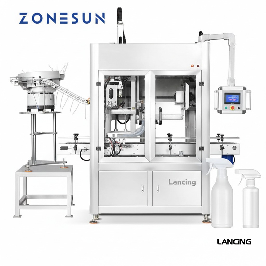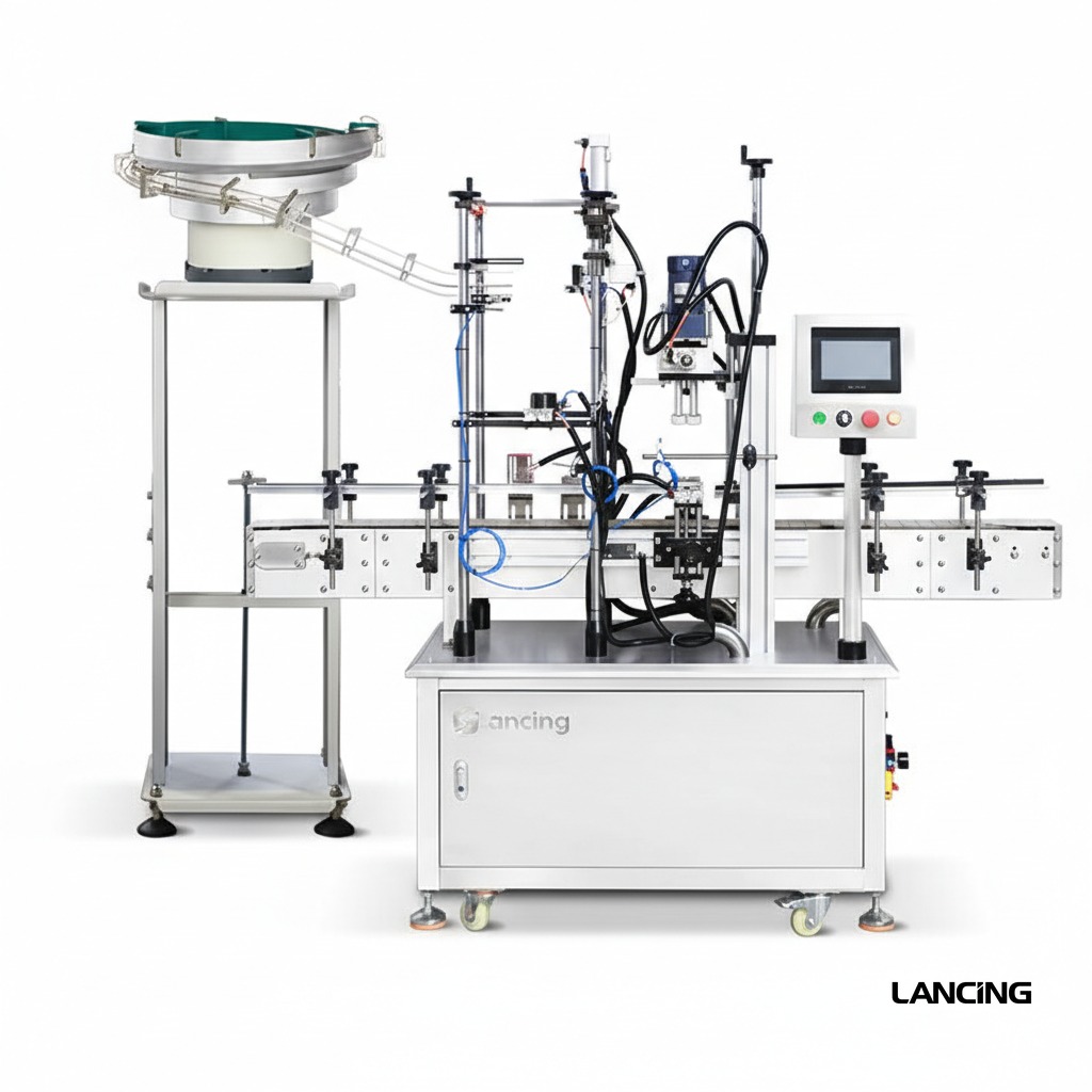
Bottle spacing
Containers are separated and guided into the machine.
Flexible inline capping
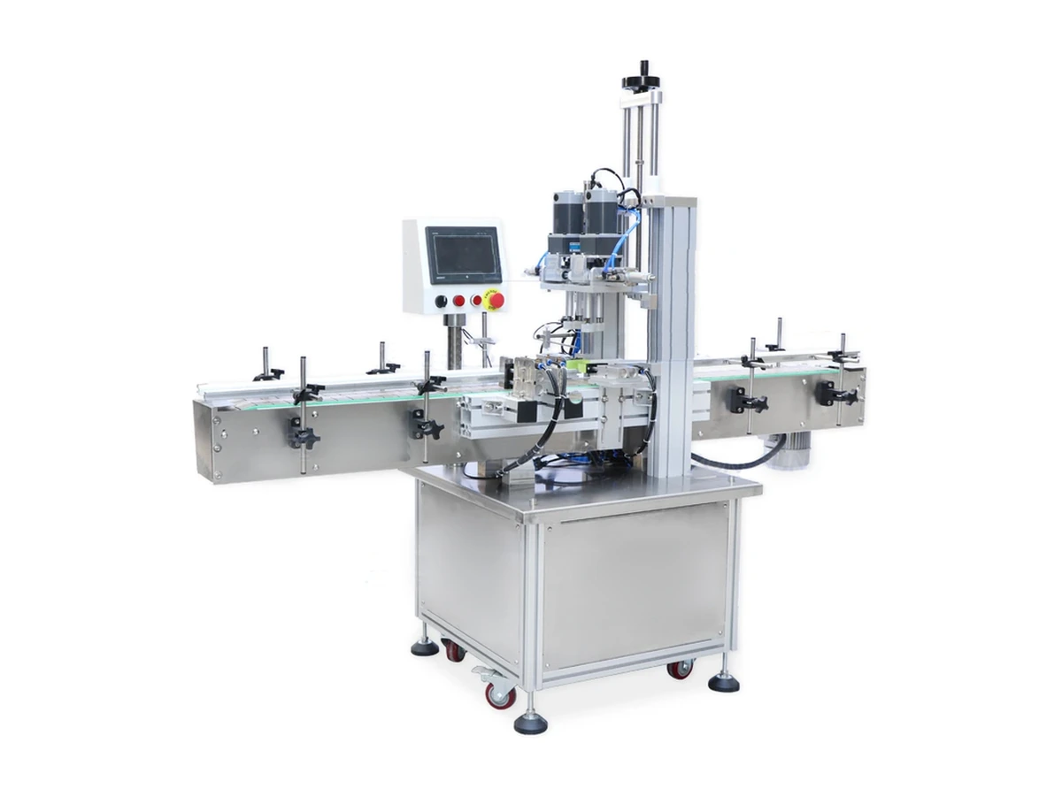
A flexible automatic screw-capping platform for suitable spray and pump closures, using in-line bottle control and powered capping modules.
Where it fits
A flexible automatic screw-capping platform for suitable spray and pump closures, using in-line bottle control and powered capping modules.
Pump capping performance is governed by the complete pack. Bottle support, dip-tube insertion, pump-head orientation and thread engagement are developed together, using approved samples and a documented production requirement.
Project specification
The final specification is developed from approved bottle and pump samples, required output, line interfaces, site standards and documented acceptance criteria.
All performance and dimensions are indicative. Exact configuration and output are subject to approved samples, product information, agreed trials and final quotation.
| Configuration | Automatic inline spray and pump screw-capping system |
|---|---|
| Output basis | Confirmed by sample trial and agreed acceptance conditions |
| Closure compatibility | Configured to approved spray, pump and screw-closure samples |
| Bottle compatibility | Configured to approved bottle samples |
| Electrical requirements | Confirmed for the final machine configuration |
| Pneumatic requirements | Confirmed after tooling and handling design |
| Footprint | Project- and conveyor-dependent; confirmed on the line layout |
Operating sequence
The final sequence is tailored to the selected closure feeder, bottle format and upstream/downstream interfaces.
Containers are separated and guided into the machine.
Pumps are manually placed or delivered by a validated feeder.
Side belts or guides stabilise each bottle through capping.
Powered wheels or heads apply the configured closure setting.
Capped product exits continuously to the next process.
Sample-led engineering
Reliable pump automation is proven with representative components rather than inferred from nominal dimensions.
Every size and shape, ideally decorated and at representative filled weight.
Production closures showing normal tube length, curvature, packing and batch variation.
Required sustained rate, shift pattern, batch size and expected line efficiency.
Torque, height, direction, leakage, cosmetic and reject acceptance criteria.
Machine views
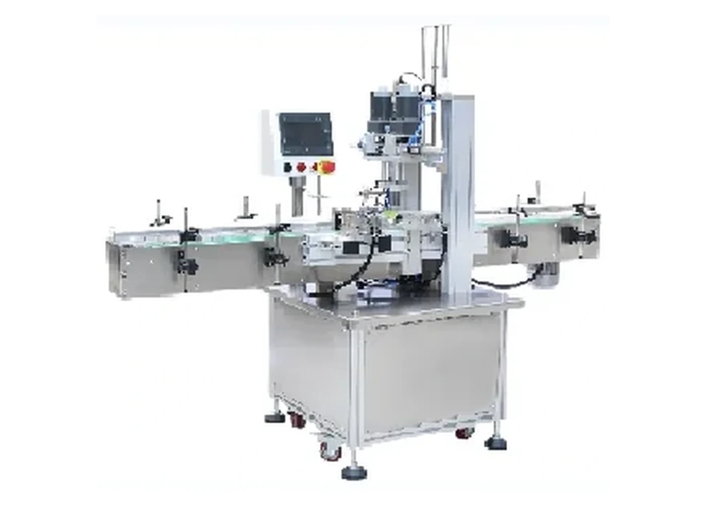
These real product photographs show representative equipment and process details. Your final configuration is confirmed against approved bottles, pumps and project requirements.
Practical answers
Every pump format behaves differently. Final machine selection and performance are confirmed through sample review and agreed trials.
Suitability depends on the complete bottle-and-pump combination, not only nominal diameter. Closure head shape, tube length and curvature, neck finish, filled weight and final presentation are reviewed before a configuration is confirmed.
Output is confirmed by sample trial. Actual sustained output depends on the approved pack, feeding method, changeover, operator or line interfaces and agreed acceptance conditions. The project quotation states the tested or warranted basis.
Usually, provided each format falls within the engineered handling range. Some changes may be tool-free; others require guides, chucks, pockets, pump transfer parts or recipe changes. Supply the complete format matrix at enquiry stage.
The method depends on the closure. Directional actuators may be oriented in the feeder, during placement, by controlled thread engagement or in a separate orientation step. Exact directional tolerance must be agreed during testing.
Send representative bottles and pumps from normal production supply, including labelled or decorated bottles where marking is a concern. Filled-weight samples or safe ballast, component technical files and expected variation are also valuable.
Related machinery
Custom trigger sprayer capper
An automatic capping system engineered for trigger sprayers and dispenser pumps whose head shape, actuator direction and long dip tube require positive orientation and bottle control.
View machine detailsGuarded automatic configuration
A guarded automatic capping platform that can be assessed for pump-compatible applications where enclosure, controlled access and an integrated production-cell format are required.
View machine detailsAutomatic inline configuration
An automatic in-line system for placing and tightening pump closures, with bottle handling, closure transfer and powered capping in one compact production cell.
View machine detailsNext step
Send sample photographs, dimensions, planned formats and target output. Physical samples are used to confirm handling and the final machine specification.
Mixed-format evidence
A flexible machine can reduce duplicate equipment, but only when each pump, spray and screw closure has an approved feeding, placement and tightening method.
| Closure family | Likely handling emphasis | Evidence needed before approval |
|---|---|---|
| Lotion or dispenser pump | Tube insertion, collar pre-threading, approved drive surface and bottle support. | Tube/neck relationship, thread-start video, head contact, closure height and torque method. |
| Spray pump | Small actuator or collar, tube control and possible directional presentation. | Orientation feature, tube entry, cosmetic contact, final direction and sustained run result. |
| Trigger sprayer | Asymmetric head, long tube and strong final directional requirement. | Specialist feeder/placement route, direction window, bottle stability and fault recovery. |
| Conventional screw cap | Cap presentation, thread start and powered belt/spindle or chuck tightening. | Cap feeder, bottle grip, torque method, cap damage and approved speed by format. |
| Manually presented closure | Operator controls orientation and insertion; machine supplies repeatable tightening. | Operator method, ergonomics, cycle time, chuck/insert and first-off quality checks. |
Belt or spindle cappers are strong options for compatible pre-applied screw closures because the bottle can continue through an inline tightening zone. A chuck head can provide defined engagement with a collar but may require indexed bottle presentation. Automatic pump placement adds separation, orientation and dip-tube insertion before either tightening method. One platform should not be described as universal unless the change parts and process for every approved closure are defined.
This page remains a pump-led comparison for a mixed closure family. Detailed trigger-sprayer selection belongs on Trigger Cappers UK. Detailed spindle and belt capping belongs on Spindle Cappers UK. Standard bottle-capping and broad machine comparisons are also available through Bottle Cappers UK and Capping Machines UK.
Create a format sheet for guides, belts, chucks, nests, feeder settings, sensor positions, recipes and acceptance checks. Store format parts by code and identify approved contact surfaces. After changeover, run a first-off pack through all relevant checks before releasing the line. Include cleaning of grip surfaces and removal of trapped components from the previous closure family.
Confirm whether closures arrive manually, from a bowl, elevator, pump feeder or existing system. Define ready, demand, fault and stop signals between the feeder, capper, filler and downstream equipment. A mixed-format machine can have different bottleneck equipment by format, so the line speed and accumulation strategy should be documented for each approved route.
Project review
Send every bottle, pump, spray head and screw cap that the platform must run, together with target output and changeover expectations.
Thread and head control
Spray and pump closures can have asymmetric heads, flexible dip tubes and limited robust contact surfaces. Define the placement angle, collar seating, pre-threading method and final tightening contact from real samples. A closure that reaches the head tilted can cross-thread even when the final torque setting is unchanged.
Use the tightening technology comparison and compatibility guide to select the trial conditions. Record actuator state, cap height, agreed torque method and cosmetic condition for each approved format.